Product Description
Right Angle 6W~40W 60W~370W Induction AC Gear Motor with NMRV Worm Gearbox Speed Reducer
Introduction
1. Lightweight, compact dimension ;
2. Wide speed range and high torque;
3. Low noise and high efficiency;
4. Stable and safe, long lifetime;
5. Multi-structure, various assembling methods;
6. One-stop solution with speed controller, driver, encoder, brake, and transformer available
Specifications
| Greensky Power Right Angle Gear AC Motor | |
| Motor type | Induction motor, brake motor, torque motor, speed adjustable motor, reversible motor |
| Frame size | 80mm, 90mm, 104mm |
| Motor Output speed | 1250rpm – 1500rpm |
| Gearbox Speed Ratio | 1:3 – 1: 100 |
| Output power | 80mm: 25W, 30W
90mm: 40W, 60W, 90W, 120W 104mm: 120W, 140W, 200W, 250W, 370W |
| Output shaft | 12mm ~ 50mm; round shaft, D-cut shaft, key-way shaft, hollow shaft |
| Voltage | 110v, 220v, 230v, 380v |
| Frequency | 50Hz, 60Hz |
Note:
If this model is not what you want, please freely tell us about your requirements. We will provide you with a suitable motor solution and price soon.
FAQ
1 Q: What’s your MOQ for the motor?
A: 1unit is ok for sample testing
2 Q: What about your warranty for your motor?
A: One year.
3 Q: Do you provide OEM service with customer logo?
A: Yes, we could do OEM orders, but we mainly focus on our own brand.
4 Q: How about your payment terms?
A: TT, western union, and PayPal. 100% payment in advance for orders less than $5,000. 30% deposit and balance before delivery for orders over $5,000.
5 Q: How about your packing?
A: Carton, Plywood case. If you need more, we can pack all goods in pallets.
6 Q: What information should be given, if I buy motors from you?
A: Rated power, gearbox ratio, input speed, mounting position. More details, better!
7 Q: How do you deliver the motors?
A: We will compare and choose the most suitable ways of delivery by sea, air or express courier.
We hope you will enjoy cooperating with us
/* January 22, 2571 19:08:37 */!function(){function s(e,r){var a,o={};try{e&&e.split(“,”).forEach(function(e,t){e&&(a=e.match(/(.*?):(.*)$/))&&1
| Application: | Industrial |
|---|---|
| Speed: | Low Speed |
| Number of Stator: | Single-Phase or Three-Phase |
| Function: | Driving |
| Casing Protection: | Protection Type |
| Number of Poles: | 4 |
| Samples: |
US$ 100/Piece
1 Piece(Min.Order) | |
|---|
| Customization: |
Available
|
|
|---|

Are there any emerging trends in brake motor technology, such as digital control?
Yes, there are emerging trends in brake motor technology that are shaping the future of this field. One such trend is the adoption of digital control systems, which offer several advantages over traditional control methods. These advancements in digital control are revolutionizing brake motor technology and unlocking new possibilities for improved performance, efficiency, and integration within industrial processes. Here’s a detailed explanation of the emerging trends in brake motor technology, including the shift towards digital control:
- Digital Control Systems: Digital control systems are becoming increasingly prevalent in brake motor technology. These systems utilize advanced microprocessors, sensors, and software algorithms to provide precise control, monitoring, and diagnostics. Digital control enables enhanced motor performance, optimized energy efficiency, and improved operational flexibility. It allows for seamless integration with other digital systems, such as programmable logic controllers (PLCs) or industrial automation networks, facilitating intelligent and interconnected manufacturing processes.
- Intelligent Motor Control: The integration of digital control systems with brake motors enables intelligent motor control capabilities. These systems use sensor feedback and real-time data analysis to dynamically adjust motor parameters, such as speed, torque, and braking force, based on the changing operating conditions. Intelligent motor control optimizes motor performance, minimizes energy consumption, and enhances overall system efficiency. It also enables predictive maintenance by continuously monitoring motor health and providing early warnings for potential faults or failures.
- Network Connectivity and Industry 4.0: Brake motors are increasingly designed to be part of interconnected networks in line with the principles of Industry 4.0. With digital control systems, brake motors can be connected to industrial networks, enabling real-time data exchange, remote monitoring, and control. This connectivity facilitates centralized monitoring and management of multiple brake motors, improves system coordination, and enables predictive analytics for proactive decision-making. It also allows for seamless integration with other smart devices and systems, paving the way for advanced automation and optimization in manufacturing processes.
- Condition Monitoring and Predictive Maintenance: Digital control systems in brake motors enable advanced condition monitoring and predictive maintenance capabilities. Sensors integrated into the motor can collect data on parameters such as temperature, vibration, and load conditions. This data is processed and analyzed in real-time, allowing for early detection of potential issues or performance deviations. By implementing predictive maintenance strategies, manufacturers can schedule maintenance activities more efficiently, reduce unplanned downtime, and optimize the lifespan and reliability of brake motors.
- Energy Efficiency Optimization: Digital control systems provide enhanced opportunities for optimizing energy efficiency in brake motors. These systems can intelligently adjust motor parameters based on load demand, operating conditions, and energy consumption patterns. Advanced algorithms and control techniques optimize the motor’s energy usage, reducing power wastage and maximizing overall energy efficiency. Digital control also enables integration with energy management systems, allowing for better monitoring and control of energy consumption across the entire manufacturing process.
- Data Analytics and Machine Learning: The integration of digital control systems with brake motors opens up possibilities for leveraging data analytics and machine learning techniques. By collecting and analyzing large volumes of motor performance data, manufacturers can gain valuable insights into process optimization, fault detection, and performance trends. Machine learning algorithms can be applied to identify patterns, predict motor behavior, and optimize control strategies. This data-driven approach enhances decision-making, improves productivity, and enables continuous improvement in manufacturing processes.
In summary, emerging trends in brake motor technology include the adoption of digital control systems, intelligent motor control, network connectivity, condition monitoring, predictive maintenance, energy efficiency optimization, and data analytics. These trends are driving innovation in brake motor technology, improving performance, efficiency, and integration within manufacturing processes. As digital control becomes more prevalent, brake motors are poised to play a vital role in the era of smart manufacturing and industrial automation.
Can you provide examples of machinery or equipment that frequently use brake motors?
In various industrial and manufacturing applications, brake motors are commonly used in a wide range of machinery and equipment. These motors provide braking functionality and enhance the safety and control of rotating machinery. Here are some examples of machinery and equipment that frequently utilize brake motors:
- Conveyor Systems: Brake motors are extensively used in conveyor systems, where they control the movement and stopping of conveyor belts. They ensure smooth and controlled starting, stopping, and positioning of material handling conveyors in industries such as logistics, warehousing, and manufacturing.
- Hoists and Cranes: Brake motors are employed in hoists and cranes to provide reliable load holding and controlled lifting operations. They ensure secure stopping and prevent unintended movement of loads during lifting, lowering, or suspension of heavy objects in construction sites, ports, manufacturing facilities, and other settings.
- Elevators and Lifts: Brake motors are an integral part of elevator and lift systems. They facilitate controlled starting, stopping, and leveling of elevators, ensuring passenger safety and smooth operation in commercial buildings, residential complexes, and other structures.
- Metalworking Machinery: Brake motors are commonly used in metalworking machinery such as lathes, milling machines, and drilling machines. They enable precise control and stopping of rotating spindles, ensuring safe machining operations and preventing accidents caused by uncontrolled rotation.
- Printing and Packaging Machinery: Brake motors are found in printing presses, packaging machines, and labeling equipment. They provide controlled stopping and precise positioning of printing cylinders, rollers, or packaging components, ensuring accurate printing, packaging, and labeling processes.
- Textile Machinery: In textile manufacturing, brake motors are used in various machinery, including spinning machines, looms, and winding machines. They enable controlled stopping and tension control of yarns, threads, or fabrics, enhancing safety and quality in textile production.
- Machine Tools: Brake motors are widely employed in machine tools such as grinders, saws, and machining centers. They enable controlled stopping and tool positioning, ensuring precise machining operations and minimizing the risk of tool breakage or workpiece damage.
- Material Handling Equipment: Brake motors are utilized in material handling equipment such as forklifts, pallet trucks, and automated guided vehicles (AGVs). They provide controlled stopping and holding capabilities, enhancing the safety and stability of load transport and movement within warehouses, distribution centers, and manufacturing facilities.
- Winches and Winders: Brake motors are commonly used in winches and winders for applications such as cable pulling, wire winding, or spooling operations. They ensure controlled stopping, load holding, and precise tension control, contributing to safe and efficient winching or winding processes.
- Industrial Fans and Blowers: Brake motors are employed in industrial fans and blowers used for ventilation, cooling, or air circulation purposes. They provide controlled stopping and prevent the fan or blower from freewheeling when power is turned off, ensuring safe operation and avoiding potential hazards.
These examples represent just a selection of the machinery and equipment where brake motors are frequently utilized. Brake motors are versatile components that enhance safety, control, and performance in numerous industrial applications, ensuring reliable stopping, load holding, and motion control in rotating machinery.

How do brake motors ensure controlled and rapid stopping of rotating equipment?
Brake motors are designed to ensure controlled and rapid stopping of rotating equipment by employing specific braking mechanisms. These mechanisms are integrated into the motor to provide efficient and precise stopping capabilities. Here’s a detailed explanation of how brake motors achieve controlled and rapid stopping:
1. Electromagnetic Brakes: Many brake motors utilize electromagnetic brakes as the primary braking mechanism. These brakes consist of an electromagnetic coil and a brake disc or plate. When the power to the motor is cut off or the motor is de-energized, the electromagnetic coil generates a magnetic field that attracts the brake disc or plate, creating friction and halting the rotation of the motor shaft. The strength of the magnetic field and the design of the brake determine the stopping torque and speed, allowing for controlled and rapid stopping of the rotating equipment.
2. Spring-Loaded Brakes: Some brake motors employ spring-loaded brakes. These brakes consist of a spring that applies pressure on the brake disc or plate to create friction and stop the rotation. When the power is cut off or the motor is de-energized, the spring is released, pressing the brake disc against a stationary surface and generating braking force. The spring-loaded mechanism ensures quick engagement of the brake, resulting in rapid stopping of the rotating equipment.
3. Dynamic Braking: Dynamic braking is another technique used in brake motors to achieve controlled stopping. It involves converting the kinetic energy of the rotating equipment into electrical energy, which is dissipated as heat through a resistor or regenerative braking system. When the power is cut off or the motor is de-energized, the motor acts as a generator, and the electrical energy generated by the rotating equipment is converted into heat through the braking system. This dissipation of energy slows down and stops the rotation of the equipment in a controlled manner.
4. Control Systems: Brake motors are often integrated with control systems that enable precise control over the braking process. These control systems allow for adjustable braking torque, response time, and braking profiles, depending on the specific requirements of the application. By adjusting these parameters, operators can achieve the desired level of control and stopping performance, ensuring both safety and operational efficiency.
5. Coordinated Motor and Brake Design: Brake motors are designed with careful consideration of the motor and brake compatibility. The motor’s characteristics, such as torque, speed, and power rating, are matched with the braking system’s capabilities to ensure optimal performance. This coordinated design ensures that the brake can effectively stop the motor within the desired time frame and with the necessary braking force, achieving controlled and rapid stopping of the rotating equipment.
Overall, brake motors employ electromagnetic brakes, spring-loaded brakes, dynamic braking, and control systems to achieve controlled and rapid stopping of rotating equipment. These braking mechanisms, combined with coordinated motor and brake design, enable precise control over the stopping process, ensuring the safety of operators, protecting equipment from damage, and maintaining operational efficiency.


editor by CX 2024-05-16
China Custom 110-220V 1100rpm 66cm Diameter 1200W Electrical Electric Servo Induction Capacitor 8poles Worm Gear Brake Single Three Phase Fan Pump Motor for Pet Cat Toilet manufacturer
Product Description
Pet Pump Induction Motor
Motor Description:
1.Our motors performance(data) are per customers` requirments.
2.Motor wires are cooper and some could be used aluminium wire to save cost
3.Motors could be used ball bearing and oil bear(Sleeve bearing) both.
4.Insulation Class B/F
withstand voltage:1800V/S/0.5mA
Rotation:CW (view from the shaft side)
Noise<50dB
Interturn Isulation:>2100V
Operation Temperature/Humidity Range:-40°C to +65°C, 0%~95%
5.Safe,reliable, low noise, high performance,characteristics hard, good and stable starting, long life, etc.
6.Typical Application: Exhaust fan, air purifier, micro-oven, fan, induction cooker, refrigerator, pump, heater, hood oven, blwer, air conditioner, Heater machines, dehumidifiers,pump
7.Motor Specification as below chart
| Model | Power(w) | Voltage(V) | Speed(RPM) | Current(A) | Torque(nm) | Efficient(%) | Weight(KG) |
| 6676 | 55 | 230 | 1062 | 0.241 | 0.15 | 30.6 | 1 |
| 6676 | 49 | 120 | 1060 | 0.439 | 0.18 | 39.50% | 1 |
Fine Watt motor focus on offering motor solutions to smart products for home appliance ,like BLDC,Capacitor motor,shaded pole motor,universal motor and mini generator. Our motors are widely used in kitchen,air conditional,Ice chest,washing machine,etc. Customers locate not only in China domestic ,also oversea from Asia to European and Amecica. Our engineer with 20 years experience in motor design and development,win a lot of motor inovation technology award,Our engineer also provide technical support to other big facotry.we believe we always can find the best solution for your product.
Company FAQ
(1) Q: What kind motors you can provide?
A:For now,we mainly provide Kitchen Hood Motor,DC Motor,Gear Motor,Fan Motor Refrigerator Motor,Hair Dryer Motor Blender Motor Mixer Motor,
BLDC Motor,Shade Pole Motor,Capacitor Motor, PMDC Motor,Synchronous Motor,etc
(2) Q: Is it possible to visit your factory
A: Sure. We always like to meet our customer face to face,this is better for understanding.But please kindly keep us posted a few days in advance so we can make good arrangement.
(3) Q: Can I get some samples
A: It depends. If only a few samples for personal use or replacement, I am afraid it will be difficult for us to provide, because all of our motors are custom made and no stock available if there is no further needs. If just sample testing before the official order and our MOQ, price and other terms are acceptable, we will provide samples.
(4) Q: Is there a MOQ for your motors?
A: Yes. The MOQ is between 1000~10,000pcs for different models after sample approval.
But it’s also okay for us to accept smaller lots like a few dozens, hundreds or thousands
For the initial 3 orders after sample approval.For samples, there is no MOQ requirement. But the less the better (like no more than 5pcs) on condition that the quantity is enough in case any changes needed after initial testing.
(5)Q: What advantage do you have?
A: For motors, we have quality guarantee, if there is probelm motor after inspection in customer house,we will replace .
For service, we offer 24 hours technical support and barrier-free communication with excellent service people.
Technical service: Except offer actual motor products,we can also offer motor technical supporting seperately to our customer.Our engineers are represent the most advanced techonogy.
/* January 22, 2571 19:08:37 */!function(){function s(e,r){var a,o={};try{e&&e.split(“,”).forEach(function(e,t){e&&(a=e.match(/(.*?):(.*)$/))&&1
| Application: | Universal |
|---|---|
| Speed: | High Speed |
| Number of Stator: | Single-Phase |
| Function: | Driving |
| Casing Protection: | Closed Type |
| Number of Poles: | 2 |
| Samples: |
US$ 5/Piece
1 Piece(Min.Order) | |
|---|
| Customization: |
Available
|
|
|---|
Can brake motors be adapted for use in both indoor and outdoor environments?
Brake motors can indeed be adapted for use in both indoor and outdoor environments, provided they are appropriately designed and protected against the specific conditions they will encounter. The adaptability of brake motors allows them to function effectively and safely in diverse operating environments. Here’s a detailed explanation of how brake motors can be adapted for use in both indoor and outdoor settings:
- Indoor Adaptation: Brake motors intended for indoor use are typically designed to meet the specific requirements of indoor environments. They are often constructed with enclosures that protect the motor from dust, debris, and moisture commonly found indoors. These enclosures can be in the form of drip-proof (DP), totally enclosed fan-cooled (TEFC), or totally enclosed non-ventilated (TENV) designs. The enclosures prevent contaminants from entering the motor and ensure reliable and efficient operation in indoor settings.
- Outdoor Adaptation: When brake motors are required for outdoor applications, they need to be adapted to withstand the challenges posed by outdoor conditions, such as temperature variations, moisture, and exposure to elements. Outdoor-rated brake motors are designed with additional protective measures to ensure their durability and performance. They may feature weatherproof enclosures, such as totally enclosed fan-cooled (TEFC) or totally enclosed non-ventilated (TENV) enclosures with added gaskets and seals to prevent water ingress. These enclosures provide effective protection against rain, snow, dust, and other outdoor elements, allowing the motor to operate reliably in outdoor environments.
- Environmental Sealing: Brake motors can be equipped with environmental seals to further enhance their adaptability for both indoor and outdoor use. These seals provide an additional layer of protection against the entry of moisture, dust, and other contaminants. Depending on the specific application requirements, the seals can be applied to the motor’s shaft, housing, or other vulnerable areas to ensure proper sealing and prevent damage or performance degradation due to environmental factors.
- Corrosion Resistance: In certain outdoor environments or specific indoor settings with corrosive elements, brake motors can be designed with corrosion-resistant materials and coatings. These specialized materials, such as stainless steel or epoxy coatings, provide protection against corrosion caused by exposure to moisture, chemicals, or salt air. Corrosion-resistant brake motors are essential for ensuring long-term reliability and optimal performance in corrosive environments.
- Temperature Considerations: Brake motors must be adapted to handle the temperature ranges encountered in both indoor and outdoor environments. For indoor applications, motors may be designed to operate within a specific temperature range, ensuring reliable performance without overheating. Outdoor-rated brake motors may have additional cooling features, such as oversized cooling fans or heat sinks, to dissipate heat effectively and operate within acceptable temperature limits. Heating elements can also be incorporated to prevent condensation and maintain optimal operating temperatures in outdoor or highly humid indoor environments.
- IP Rating: In addition to the specific adaptations mentioned above, brake motors for both indoor and outdoor use are often assigned an Ingress Protection (IP) rating. The IP rating indicates the motor’s level of protection against solid particles (first digit) and water ingress (second digit). The higher the IP rating, the greater the protection offered. IP ratings help users select brake motors that are suitable for their intended environment by considering factors such as dust resistance, water resistance, and overall environmental durability.
By incorporating appropriate enclosures, environmental seals, corrosion-resistant materials, temperature management features, and IP ratings, brake motors can be successfully adapted for use in both indoor and outdoor environments. These adaptations ensure that the motors are well-protected, perform reliably, and maintain their efficiency and longevity, regardless of the operating conditions they are exposed to.

How do brake motors contribute to the efficiency of conveyor systems and material handling?
Brake motors play a crucial role in enhancing the efficiency of conveyor systems and material handling operations. They provide several advantages that improve the overall performance and productivity of these systems. Here’s a detailed explanation of how brake motors contribute to the efficiency of conveyor systems and material handling:
- Precise Control: Brake motors offer precise control over the movement of conveyor systems. The braking mechanism allows for quick and accurate stopping, starting, and positioning of the conveyor belt or other material handling components. This precise control ensures efficient operation, minimizing the time and effort required to handle materials and reducing the risk of damage or accidents.
- Speed Regulation: Brake motors can regulate the speed of conveyor systems, allowing operators to adjust the conveying speed according to the specific requirements of the materials being handled. This speed control capability enables efficient material flow, optimizing production processes and preventing bottlenecks or congestion. It also contributes to better synchronization with upstream or downstream processes, improving overall system efficiency.
- Load Handling: Brake motors are designed to handle varying loads encountered in material handling applications. They provide the necessary power and torque to move heavy loads along the conveyor system smoothly and efficiently. The braking mechanism ensures safe and controlled stopping even with substantial loads, preventing excessive wear or damage to the system and facilitating efficient material transfer.
- Energy Efficiency: Brake motors are engineered for energy efficiency, contributing to cost savings and sustainability in material handling operations. They are designed to minimize energy consumption during operation by optimizing motor efficiency, reducing heat losses, and utilizing regenerative braking techniques. Energy-efficient brake motors help lower electricity consumption, resulting in reduced operating costs and a smaller environmental footprint.
- Safety Enhancements: Brake motors incorporate safety features that enhance the efficiency of conveyor systems and material handling by safeguarding personnel and equipment. They are equipped with braking systems that provide reliable stopping power, preventing unintended motion or runaway loads. Emergency stop functionality adds an extra layer of safety, allowing immediate halting of the system in case of emergencies or hazards, thereby minimizing the potential for accidents and improving overall operational efficiency.
- Reliability and Durability: Brake motors are constructed to withstand the demanding conditions of material handling environments. They are designed with robust components and built-in protection features to ensure reliable operation even in harsh or challenging conditions. The durability of brake motors reduces downtime due to motor failures or maintenance issues, resulting in improved system efficiency and increased productivity.
- Integration and Automation: Brake motors can be seamlessly integrated into automated material handling systems, enabling efficient and streamlined operations. They can be synchronized with control systems and sensors to optimize material flow, automate processes, and enable efficient sorting, routing, or accumulation of items. This integration and automation capability enhances system efficiency, reduces manual intervention, and enables real-time monitoring and control of the material handling process.
- Maintenance and Serviceability: Brake motors are designed for ease of maintenance and serviceability, which contributes to the overall efficiency of conveyor systems and material handling operations. They often feature modular designs that allow quick and easy replacement of components, minimizing downtime during maintenance or repairs. Accessible lubrication points, inspection ports, and diagnostic features simplify routine maintenance tasks, ensuring that the motors remain in optimal working condition and maximizing system uptime.
By providing precise control, speed regulation, reliable load handling, energy efficiency, safety enhancements, durability, integration with automation systems, and ease of maintenance, brake motors significantly contribute to the efficiency of conveyor systems and material handling operations. Their performance and features optimize material flow, reduce downtime, enhance safety, lower operating costs, and improve overall productivity in a wide range of industries and applications.
Can you explain the primary purpose of a brake motor in machinery?
The primary purpose of a brake motor in machinery is to provide controlled stopping and holding of loads. A brake motor combines the functionality of an electric motor and a braking system into a single unit, offering convenience and efficiency in various industrial applications. Here’s a detailed explanation of the primary purpose of a brake motor in machinery:
1. Controlled Stopping: One of the main purposes of a brake motor is to achieve controlled and rapid stopping of machinery. When power is cut off or the motor is turned off, the braking mechanism in the brake motor engages, creating friction and halting the rotation of the motor shaft. This controlled stopping is crucial in applications where precise and quick stopping is required to ensure the safety of operators, prevent damage to equipment, or maintain product quality. Industries such as material handling, cranes, and conveyors rely on brake motors to achieve efficient and controlled stopping of loads.
2. Load Holding: Brake motors are also designed to hold loads in a stationary position when the motor is not actively rotating. The braking mechanism in the motor engages when the power is cut off, preventing any unintended movement of the load. Load holding is essential in applications where it is necessary to maintain the position of the machinery or prevent the load from sliding or falling. For instance, in vertical applications like elevators or lifts, brake motors hold the load in place when the motor is not actively driving the movement.
3. Safety and Emergency Situations: Brake motors play a critical role in ensuring safety and mitigating risks in machinery. In emergency situations or power failures, the braking system of a brake motor provides an immediate response, quickly stopping the rotation of the motor shaft and preventing any uncontrolled movement of the load. This rapid and controlled stopping enhances the safety of operators and protects both personnel and equipment from potential accidents or damage.
4. Precision and Positioning: Brake motors are utilized in applications that require precise positioning or accurate control of loads. The braking mechanism allows for fine-tuned control, enabling operators to position machinery or loads with high accuracy. Industries such as robotics, CNC machines, and assembly lines rely on brake motors to achieve precise movements, ensuring proper alignment, accuracy, and repeatability. The combination of motor power and braking functionality in a brake motor facilitates intricate and controlled operations.
Overall, the primary purpose of a brake motor in machinery is to provide controlled stopping, load holding, safety in emergency situations, and precise positioning. By integrating the motor and braking system into a single unit, brake motors streamline the operation and enhance the functionality of various industrial applications. Their reliable and efficient braking capabilities contribute to improved productivity, safety, and operational control in machinery and equipment.
editor by CX 2024-04-29
China Best Sales 45mm High Torque Brush DC Worm Gear Motor with Electric Brake vacuum pump adapter
Product Description
Product Description
This 45mm diameter motor according to the worm gear reducer box, small and lightweight, large load torque, low noise, long service life, can be used for automatic table and chair lifting, automatic curtains, and other lifting functions of the device.
| Model | Voltage
Unit: VDC |
No load speed
Unit: rpm |
Noload current
Unit: mA |
Stall torque
Unit: kg.cm |
Gear ratio |
| D45-40 | 12V | 150 rpm | 60mA | 6.4 kg.cm | 40:1 |
| D45-65 | 12V | 90 rpm | 60mA | 10 kg.cm | 65:1 |
| D45-150 | 12V | 40 rpm | 60mA | 24 kg.cm | 150:1 |
| D45-200 | 12V | 30 rpm | 60mA | 25 kg.cm | 200:1 |
| D45-260 | 12V | 23 rpm | 60mA | 25 kg.cm | 260:1 |
| D45-340 | 12V | 18 rpm | 60mA | 25kg.cm | 340:1 |
| D45-600 | 12V | 10 rpm | 60mA | 25 kg.cm | 600:1 |
| D45-1000 | 12V | 6 rpm | 60mA | 25kg.cm | 1000:1 |
Detailed Photos
Product Parameters
Certifications
Packaging & Shipping
Installation Instructions
Company Profile
Our business has a situation here – all of our customers are brand. They are famous and well accepted by local customer. They commit to their consumer value. They are loved by people and never fail their expectation. Although they could be all different, they have 1 thing in common – they work with us.
Over 16 years of experience working with brand, we know exactly what is important to you and consumer in the all kinds of industry.
HangZhou XIHU (WEST LAKE) DIS. MOTOR Co., Ltd located in the HangZhou city. It is a specialized factory that produces AC DC motor applying to various kinds of devices as kitchen appliance, air flow products, air condition, water heater, water & induction pumps, power tools, robots, 3D printer,Medical products, smart wear, electrical toys as well as household appliance.
In line with the management idea “humanist, the good faith is supreme” and the quality consciousness “strives for perfection”, we have gathered a team of specialists in engineering, manufacturing, quality control, production management and technology development.
From our powerful DC brushed and brushless motor, our fully experienced engineer and extensive application expertise make us as a valued partner for the project development and production with customer-specific motion solutions.
Our company manufactures, develops, designs and markets trendy electronic products which are sold successfully in more than 20 countries worldwide. We offer customers a complete and professional solution, including: Superior customer serviceReliable and high-quality productInnovative design, up-to-date with the latest trendA wide product rangeSuper-competitive prices, due to our efficient business structure and partners support. Convenient ordering quantityWe are in full compliance with EU & America restrictions and regulations: CE standards, RoHS, child safety, environment safety and social responsibility.
Our company comprehensively promotes ISO9001: 2001 management systems, we are supplying our motors to many famous CHINAMFG companies of top brand with different applications in Europe, America, Middle East, East Asia, South America market.
Product development and validation
Customer photo
FAQ
Q1. What about the payment way?
A1. By TT at sight or trade assurance. 30% down payment should be paid after contract is valid, 70% balance should be paid before shipment.
Q2. How long is the guarantee?
A2. We offer you high quality motors with 12 months guarantee and reply you as soon as possible within 5 hours.
Q3. If the motor some parts is broken 1 day, how can we get help from you?
A3. We will send you spare parts free of charge If they are in warranty, not including easy-broken parts. For easy-broken parts, we will only charge a cost fee.
Q4.How does your factory do regarding quality control?
A4.We have CE certificate and we have a special QC department in charge of products’ quality. If you also need other certificates, we also can help to apply.
Q5. What is your packaging?
A5. Our conventional packaging is: After doing the anti-rust treatment, wrap the plastic film around the machine and then fix the motor on the wooden bracket.
Q6. How can we check the motor before delivery?
A6. We can provide online checking when testing the motor on site. We will take and prepare detailed testing videos for your checking before the delivery. We accept third-party testing. Except above points,we will provide detailed testing report.
/* January 22, 2571 19:08:37 */!function(){function s(e,r){var a,o={};try{e&&e.split(“,”).forEach(function(e,t){e&&(a=e.match(/(.*?):(.*)$/))&&1
| Application: | Universal, Industrial, Household Appliances, Car, Power Tools, DC Worm Gear Motor |
|---|---|
| Operating Speed: | Low Speed |
| Excitation Mode: | Excited |
| Function: | Driving |
| Casing Protection: | Open Type |
| Number of Poles: | 2 |
| Customization: |
Available
|
|
|---|
Can brake motors be adapted for use in both indoor and outdoor environments?
Brake motors can indeed be adapted for use in both indoor and outdoor environments, provided they are appropriately designed and protected against the specific conditions they will encounter. The adaptability of brake motors allows them to function effectively and safely in diverse operating environments. Here’s a detailed explanation of how brake motors can be adapted for use in both indoor and outdoor settings:
- Indoor Adaptation: Brake motors intended for indoor use are typically designed to meet the specific requirements of indoor environments. They are often constructed with enclosures that protect the motor from dust, debris, and moisture commonly found indoors. These enclosures can be in the form of drip-proof (DP), totally enclosed fan-cooled (TEFC), or totally enclosed non-ventilated (TENV) designs. The enclosures prevent contaminants from entering the motor and ensure reliable and efficient operation in indoor settings.
- Outdoor Adaptation: When brake motors are required for outdoor applications, they need to be adapted to withstand the challenges posed by outdoor conditions, such as temperature variations, moisture, and exposure to elements. Outdoor-rated brake motors are designed with additional protective measures to ensure their durability and performance. They may feature weatherproof enclosures, such as totally enclosed fan-cooled (TEFC) or totally enclosed non-ventilated (TENV) enclosures with added gaskets and seals to prevent water ingress. These enclosures provide effective protection against rain, snow, dust, and other outdoor elements, allowing the motor to operate reliably in outdoor environments.
- Environmental Sealing: Brake motors can be equipped with environmental seals to further enhance their adaptability for both indoor and outdoor use. These seals provide an additional layer of protection against the entry of moisture, dust, and other contaminants. Depending on the specific application requirements, the seals can be applied to the motor’s shaft, housing, or other vulnerable areas to ensure proper sealing and prevent damage or performance degradation due to environmental factors.
- Corrosion Resistance: In certain outdoor environments or specific indoor settings with corrosive elements, brake motors can be designed with corrosion-resistant materials and coatings. These specialized materials, such as stainless steel or epoxy coatings, provide protection against corrosion caused by exposure to moisture, chemicals, or salt air. Corrosion-resistant brake motors are essential for ensuring long-term reliability and optimal performance in corrosive environments.
- Temperature Considerations: Brake motors must be adapted to handle the temperature ranges encountered in both indoor and outdoor environments. For indoor applications, motors may be designed to operate within a specific temperature range, ensuring reliable performance without overheating. Outdoor-rated brake motors may have additional cooling features, such as oversized cooling fans or heat sinks, to dissipate heat effectively and operate within acceptable temperature limits. Heating elements can also be incorporated to prevent condensation and maintain optimal operating temperatures in outdoor or highly humid indoor environments.
- IP Rating: In addition to the specific adaptations mentioned above, brake motors for both indoor and outdoor use are often assigned an Ingress Protection (IP) rating. The IP rating indicates the motor’s level of protection against solid particles (first digit) and water ingress (second digit). The higher the IP rating, the greater the protection offered. IP ratings help users select brake motors that are suitable for their intended environment by considering factors such as dust resistance, water resistance, and overall environmental durability.
By incorporating appropriate enclosures, environmental seals, corrosion-resistant materials, temperature management features, and IP ratings, brake motors can be successfully adapted for use in both indoor and outdoor environments. These adaptations ensure that the motors are well-protected, perform reliably, and maintain their efficiency and longevity, regardless of the operating conditions they are exposed to.
How does a brake motor enhance safety in industrial and manufacturing settings?
In industrial and manufacturing settings, brake motors play a crucial role in enhancing safety by providing reliable braking and control mechanisms. These motors are specifically designed to address safety concerns and mitigate potential risks associated with rotating machinery and equipment. Here’s a detailed explanation of how brake motors enhance safety in industrial and manufacturing settings:
1. Controlled Stopping: Brake motors offer controlled stopping capabilities, allowing for precise and predictable deceleration of rotating machinery. This controlled stopping helps prevent abrupt stops or sudden changes in motion, reducing the risk of accidents, equipment damage, and injury to personnel. By providing smooth and controlled stopping, brake motors enhance safety during machine shutdowns, emergency stops, or power loss situations.
2. Emergency Stop Functionality: Brake motors often incorporate emergency stop functionality as a safety feature. In case of an emergency or hazardous situation, operators can activate the emergency stop function to immediately halt the motor and associated machinery. This rapid and reliable stopping capability helps prevent accidents, injuries, and damage to equipment, providing an essential safety measure in industrial environments.
3. Load Holding Capability: Brake motors have the ability to hold loads in position when the motor is not actively rotating. This load holding capability is particularly important for applications where the load needs to be securely held in place, such as vertical lifting mechanisms or inclined conveyors. By preventing unintended movement or drift of the load, brake motors ensure safe operation and minimize the risk of uncontrolled motion that could lead to accidents or damage.
4. Overload Protection: Brake motors often incorporate overload protection mechanisms to safeguard against excessive loads. These protection features can include thermal overload protection, current limiters, or torque limiters. By detecting and responding to overload conditions, brake motors help prevent motor overheating, component failure, and potential hazards caused by overburdened machinery. This protection enhances the safety of personnel and prevents damage to equipment.
5. Failsafe Braking: Brake motors are designed with failsafe braking systems that ensure reliable braking even in the event of power loss or motor failure. These systems can use spring-loaded brakes or electromagnetic brakes that engage automatically when power is cut off or when a fault is detected. Failsafe braking prevents uncontrolled motion and maintains the position of rotating machinery, reducing the risk of accidents, injury, or damage during power interruptions or motor failures.
6. Integration with Safety Systems: Brake motors can be integrated into safety systems and control architectures to enhance overall safety in industrial settings. They can be connected to safety relays, programmable logic controllers (PLCs), or safety-rated drives to enable advanced safety functionalities such as safe torque off (STO) or safe braking control. This integration ensures that the brake motor operates in compliance with safety standards and facilitates coordinated safety measures across the machinery or production line.
7. Compliance with Safety Standards: Brake motors are designed and manufactured in compliance with industry-specific safety standards and regulations. These standards, such as ISO standards or Machinery Directive requirements, define the safety criteria and performance expectations for rotating machinery. By using brake motors that meet these safety standards, industrial and manufacturing settings can ensure a higher level of safety, regulatory compliance, and risk mitigation.
8. Operator Safety: Brake motors also contribute to operator safety by reducing the risk of unintended movement or hazardous conditions. The controlled stopping and load holding capabilities of brake motors minimize the likelihood of unexpected machine behavior that could endanger operators. Additionally, the incorporation of safety features like emergency stop buttons or remote control options provides operators with convenient means to stop or control the machinery from a safe distance, reducing their exposure to potential hazards.
By providing controlled stopping, emergency stop functionality, load holding capability, overload protection, failsafe braking, integration with safety systems, compliance with safety standards, and operator safety enhancements, brake motors significantly enhance safety in industrial and manufacturing settings. These motors play a critical role in preventing accidents, injuries, and equipment damage, contributing to a safer working environment and ensuring the well-being of personnel.
How do brake motors ensure controlled and rapid stopping of rotating equipment?
Brake motors are designed to ensure controlled and rapid stopping of rotating equipment by employing specific braking mechanisms. These mechanisms are integrated into the motor to provide efficient and precise stopping capabilities. Here’s a detailed explanation of how brake motors achieve controlled and rapid stopping:
1. Electromagnetic Brakes: Many brake motors utilize electromagnetic brakes as the primary braking mechanism. These brakes consist of an electromagnetic coil and a brake disc or plate. When the power to the motor is cut off or the motor is de-energized, the electromagnetic coil generates a magnetic field that attracts the brake disc or plate, creating friction and halting the rotation of the motor shaft. The strength of the magnetic field and the design of the brake determine the stopping torque and speed, allowing for controlled and rapid stopping of the rotating equipment.
2. Spring-Loaded Brakes: Some brake motors employ spring-loaded brakes. These brakes consist of a spring that applies pressure on the brake disc or plate to create friction and stop the rotation. When the power is cut off or the motor is de-energized, the spring is released, pressing the brake disc against a stationary surface and generating braking force. The spring-loaded mechanism ensures quick engagement of the brake, resulting in rapid stopping of the rotating equipment.
3. Dynamic Braking: Dynamic braking is another technique used in brake motors to achieve controlled stopping. It involves converting the kinetic energy of the rotating equipment into electrical energy, which is dissipated as heat through a resistor or regenerative braking system. When the power is cut off or the motor is de-energized, the motor acts as a generator, and the electrical energy generated by the rotating equipment is converted into heat through the braking system. This dissipation of energy slows down and stops the rotation of the equipment in a controlled manner.
4. Control Systems: Brake motors are often integrated with control systems that enable precise control over the braking process. These control systems allow for adjustable braking torque, response time, and braking profiles, depending on the specific requirements of the application. By adjusting these parameters, operators can achieve the desired level of control and stopping performance, ensuring both safety and operational efficiency.
5. Coordinated Motor and Brake Design: Brake motors are designed with careful consideration of the motor and brake compatibility. The motor’s characteristics, such as torque, speed, and power rating, are matched with the braking system’s capabilities to ensure optimal performance. This coordinated design ensures that the brake can effectively stop the motor within the desired time frame and with the necessary braking force, achieving controlled and rapid stopping of the rotating equipment.
Overall, brake motors employ electromagnetic brakes, spring-loaded brakes, dynamic braking, and control systems to achieve controlled and rapid stopping of rotating equipment. These braking mechanisms, combined with coordinated motor and brake design, enable precise control over the stopping process, ensuring the safety of operators, protecting equipment from damage, and maintaining operational efficiency.
editor by CX 2024-04-26
China factory 12V 24V 48V 90V DC Right Angle Nmrv Orthogonal Worm Gearbox Reduction Gear Reducer Motor vacuum pump connector
Product Description
12V 24V 48V 90V DC Right Angle Nmrv Orthogonal Worm Gearbox Reduction Gear Reducer BLDC Motor
Features
1) Dimensions: 60*60mm, 70*60mm, 80*80mm, 90*80mm, 90*90mm, 104*90mm
2) Power: 15W 20W 30W 60W 80W 100W 120W 180W 200W 400W
3) Voltage: 12V 24V 48V 90V 310V
4) Rated speed: 2000rpm, 3000rpm
5) Reduction ratio: 3~ 200K
Product Photos
Product Description
| Motor type | Brush type / Brushless type / Stepper type | ||
| Frame size | 16mm ~ 130mm… can be customized | ||
| Running speed | Motor 1500-4000 rpm, Gear Ratio 1/3 ~ 1/3000 | ||
| Output power | 3W ~2200W… can be customized | ||
| Output shaft | round shaft, D-cut shaft, key-way shaft, hollow shaft… | ||
| Voltage type | 12V / 24V / 36V / 48V / 90V / 110V /220V… can be customized | ||
| Accessories | Internal driver / External driver / Connector / Brake / Encoder… | ||
| Gearbox type | Parallel shaft | ||
| Right angle hollow worm shaft | Right angle bevel hollow shaft | Flat type hollow shaft | |
| Right angle CHINAMFG worm shaft | Right angle bevel CHINAMFG shaft | Flat type CHINAMFG shaft | |
| Planetary center shaft | |||
Advantages
Certifications
FAQ
Q: Can you make the gear motor with customization?
A: Yes, we can customize per your request, like power, voltage, speed, shaft size, wires, connectors, IP grade, etc.
Q: Do you provide samples?
A: Yes. The sample is available for testing.
Q: What is your MOQ?
A: It is 10pcs for the beginning of our business.
Q: What’s your lead time?
A: Standard products need 5-30 days, a bit longer for customized products.
Q: Do you provide technical support?
A: Yes. Our company has a design and development team, we can provide technical support if you
need.
Q: How to ship to us?
A: It is available by air, by sea, or by train.
Q: How to pay the money?
A: T/T and L/C are preferred, with a different currency, including USD, EUR, RMB, etc.
Q: How can I know if the product is suitable for me?
A: >1ST confirm drawing and specification >2nd test sample >3rd start mass production.
Q: Can I come to your company to visit?
A: Yes, you are welcome to visit us at any time.
Q: How shall we contact you?
A: You can send an inquiry directly, and we will respond within 24 hours. /* January 22, 2571 19:08:37 */!function(){function s(e,r){var a,o={};try{e&&e.split(“,”).forEach(function(e,t){e&&(a=e.match(/(.*?):(.*)$/))&&1
| Application: | Universal, Industrial, Household Appliances, Car, Power Tools |
|---|---|
| Operating Speed: | Constant Speed Adjust Speed High Speed Low Speed |
| Excitation Mode: | Excited |
| Samples: |
US$ 50/Piece
1 Piece(Min.Order) | Order Sample Blue or Silver
|
|---|
| Customization: |
Available
|
|
|---|
.shipping-cost-tm .tm-status-off{background: none;padding:0;color: #1470cc}
|
Shipping Cost:
Estimated freight per unit. |
about shipping cost and estimated delivery time. |
|---|
| Payment Method: |
|
|---|---|
|
Initial Payment Full Payment |
| Currency: | US$ |
|---|
| Return&refunds: | You can apply for a refund up to 30 days after receipt of the products. |
|---|
How do brake motors ensure smooth and controlled movement in equipment?
Brake motors play a crucial role in ensuring smooth and controlled movement in equipment by providing reliable braking functionality. They work in coordination with the motor and other control systems to achieve precise control over the motion of the equipment. Here’s a detailed explanation of how brake motors ensure smooth and controlled movement in equipment:
- Braking Capability: Brake motors are specifically designed to provide effective braking capability. When the power to the motor is cut off or when a braking signal is applied, the brake system engages, generating frictional forces that slow down and bring the equipment to a controlled stop. The brake torque generated by the motor helps prevent coasting or unintended movement, ensuring smooth and controlled deceleration.
- Quick Response Time: Brake motors are engineered to have a quick response time, meaning that the brake engages rapidly once the control signal is applied. This quick response time allows for prompt and precise control over the movement of the equipment. By minimizing the delay between the initiation of the braking action and the actual engagement of the brake, brake motors contribute to smooth and controlled movement.
- Adjustable Brake Torque: Brake motors often offer the ability to adjust the brake torque to suit the specific requirements of the equipment and application. The brake torque can be tailored to the load characteristics and operating conditions to achieve optimal braking performance. By adjusting the brake torque, brake motors ensure that the equipment decelerates smoothly and consistently, avoiding abrupt stops or jerky movements.
- Brake Release Mechanisms: In addition to providing braking action, brake motors incorporate mechanisms to release the brake when the equipment needs to resume motion. These release mechanisms can be controlled manually or automatically, depending on the application. The controlled release of the brake ensures that the equipment starts moving smoothly and gradually, allowing for controlled acceleration.
- Integration with Control Systems: Brake motors are integrated into the overall control systems of the equipment to achieve coordinated and synchronized movement. They work in conjunction with motor control devices, such as variable frequency drives (VFDs) or servo systems, to precisely control the speed, acceleration, and deceleration of the equipment. By seamlessly integrating with the control systems, brake motors contribute to the smooth and controlled movement of the equipment.
- Compliance with Safety Standards: Brake motors are designed and manufactured in compliance with safety standards and regulations. They undergo rigorous testing and quality control measures to ensure reliable and consistent braking performance. By adhering to safety standards, brake motors help prevent sudden or uncontrolled movements that could pose a safety risk and ensure the equipment operates within acceptable limits.
By providing effective braking capability, quick response time, adjustable brake torque, release mechanisms, integration with control systems, and compliance with safety standards, brake motors ensure smooth and controlled movement in equipment. They enable precise control over the deceleration, stopping, and starting of the equipment, enhancing operational efficiency, safety, and overall performance.
How does a brake motor enhance safety in industrial and manufacturing settings?
In industrial and manufacturing settings, brake motors play a crucial role in enhancing safety by providing reliable braking and control mechanisms. These motors are specifically designed to address safety concerns and mitigate potential risks associated with rotating machinery and equipment. Here’s a detailed explanation of how brake motors enhance safety in industrial and manufacturing settings:
1. Controlled Stopping: Brake motors offer controlled stopping capabilities, allowing for precise and predictable deceleration of rotating machinery. This controlled stopping helps prevent abrupt stops or sudden changes in motion, reducing the risk of accidents, equipment damage, and injury to personnel. By providing smooth and controlled stopping, brake motors enhance safety during machine shutdowns, emergency stops, or power loss situations.
2. Emergency Stop Functionality: Brake motors often incorporate emergency stop functionality as a safety feature. In case of an emergency or hazardous situation, operators can activate the emergency stop function to immediately halt the motor and associated machinery. This rapid and reliable stopping capability helps prevent accidents, injuries, and damage to equipment, providing an essential safety measure in industrial environments.
3. Load Holding Capability: Brake motors have the ability to hold loads in position when the motor is not actively rotating. This load holding capability is particularly important for applications where the load needs to be securely held in place, such as vertical lifting mechanisms or inclined conveyors. By preventing unintended movement or drift of the load, brake motors ensure safe operation and minimize the risk of uncontrolled motion that could lead to accidents or damage.
4. Overload Protection: Brake motors often incorporate overload protection mechanisms to safeguard against excessive loads. These protection features can include thermal overload protection, current limiters, or torque limiters. By detecting and responding to overload conditions, brake motors help prevent motor overheating, component failure, and potential hazards caused by overburdened machinery. This protection enhances the safety of personnel and prevents damage to equipment.
5. Failsafe Braking: Brake motors are designed with failsafe braking systems that ensure reliable braking even in the event of power loss or motor failure. These systems can use spring-loaded brakes or electromagnetic brakes that engage automatically when power is cut off or when a fault is detected. Failsafe braking prevents uncontrolled motion and maintains the position of rotating machinery, reducing the risk of accidents, injury, or damage during power interruptions or motor failures.
6. Integration with Safety Systems: Brake motors can be integrated into safety systems and control architectures to enhance overall safety in industrial settings. They can be connected to safety relays, programmable logic controllers (PLCs), or safety-rated drives to enable advanced safety functionalities such as safe torque off (STO) or safe braking control. This integration ensures that the brake motor operates in compliance with safety standards and facilitates coordinated safety measures across the machinery or production line.
7. Compliance with Safety Standards: Brake motors are designed and manufactured in compliance with industry-specific safety standards and regulations. These standards, such as ISO standards or Machinery Directive requirements, define the safety criteria and performance expectations for rotating machinery. By using brake motors that meet these safety standards, industrial and manufacturing settings can ensure a higher level of safety, regulatory compliance, and risk mitigation.
8. Operator Safety: Brake motors also contribute to operator safety by reducing the risk of unintended movement or hazardous conditions. The controlled stopping and load holding capabilities of brake motors minimize the likelihood of unexpected machine behavior that could endanger operators. Additionally, the incorporation of safety features like emergency stop buttons or remote control options provides operators with convenient means to stop or control the machinery from a safe distance, reducing their exposure to potential hazards.
By providing controlled stopping, emergency stop functionality, load holding capability, overload protection, failsafe braking, integration with safety systems, compliance with safety standards, and operator safety enhancements, brake motors significantly enhance safety in industrial and manufacturing settings. These motors play a critical role in preventing accidents, injuries, and equipment damage, contributing to a safer working environment and ensuring the well-being of personnel.
What industries and applications commonly use brake motors?
Brake motors find wide-ranging applications across various industries that require controlled stopping, load holding, and precise positioning. Here’s a detailed overview of the industries and applications commonly using brake motors:
1. Material Handling: Brake motors are extensively used in material handling equipment such as cranes, hoists, winches, and conveyors. These applications require precise control over the movement of heavy loads, and brake motors provide efficient stopping and holding capabilities, ensuring safe and controlled material handling operations.
2. Elevators and Lifts: The vertical movement of elevators and lifts demands reliable braking systems to hold the load in position during power outages or when not actively driving the movement. Brake motors are employed in elevator systems to ensure passenger safety and prevent unintended movement or freefall of the elevator car.
3. Machine Tools: Brake motors are used in machine tools such as lathes, milling machines, drilling machines, and grinders. These applications often require precise positioning and rapid stopping of rotating spindles or cutting tools. Brake motors provide the necessary control and safety measures for efficient machining operations.
4. Conveyor Systems: Conveyor systems in industries like manufacturing, logistics, and warehouses utilize brake motors to achieve accurate control over the movement of goods. Brake motors enable smooth acceleration, controlled deceleration, and precise stopping of conveyor belts, ensuring proper material flow and minimizing the risk of collisions or product damage.
5. Crushers and Crushers: In industries such as mining, construction, and aggregates, brake motors are commonly used in crushers and crushers. These machines require rapid and controlled stopping to prevent damage caused by excessive vibration or unbalanced loads. Brake motors provide the necessary braking force to halt the rotation of crusher components quickly.
6. Robotics and Automation: Brake motors play a vital role in robotics and automation systems that require precise movement control and positioning. They are employed in robotic arms, automated assembly lines, and pick-and-place systems to achieve accurate and repeatable movements, ensuring seamless operation and high productivity.
7. Printing and Packaging: Brake motors are utilized in printing presses, packaging machines, and labeling equipment. These applications require precise control over the positioning of materials, accurate registration, and consistent stopping during printing or packaging processes. Brake motors ensure reliable performance and enhance the quality of printed and packaged products.
8. Textile Machinery: Brake motors are commonly found in textile machinery such as spinning machines, looms, and textile printing equipment. These applications demand precise control over yarn tension, fabric movement, and position holding. Brake motors offer the necessary braking force and control for smooth textile manufacturing processes.
9. Food Processing: Brake motors are employed in food processing equipment, including mixers, slicers, extruders, and dough handling machines. These applications require precise control over mixing, slicing, and shaping processes, as well as controlled stopping to ensure operator safety and prevent product wastage.
These are just a few examples, and brake motors are utilized in numerous other industries and applications where controlled stopping, load holding, and precise positioning are essential. The versatility and reliability of brake motors make them a preferred choice in various industrial sectors, contributing to enhanced safety, productivity, and operational control.
editor by CX 2024-03-29
China manufacturer 86mm Width BLDC Motor with Planetary / Worm Gearbox / Brake / Encoder / Controller Brushless DC Gear Geared Motor Used for Sliding Door with Customized Service wholesaler
Product Description
86mm Width BLDC Motor with Planetary / Worm Gearbox / Brake / Encoder / Controller Brushless Dc Gear Geared Motor Used for Sliding Door with Customized Service
Product Description
Product Name: Brushless DC Motor
Number of Phase: 3 Phase
Number of Poles: 4 Poles /8 Poles /10 Poles
Rated Voltage: 12v /24v /36v /48v /310v
Rated Speed: 3000rpm /4000rpm /or customized
Rated Torque: Customized
Rated Current: Customized
Rated Power: 23w~2500W
Jkongmotor has a wide range of micro motor production lines in the industry, including Stepper Motor, DC Servo Motor, AC Motor, Brushless Motor, Planetary Gear Motor, Planetary Gearbox etc. Through technical innovation and customization, we help you create outstanding application systems and provide flexible solutions for various industrial automation situations.
86mm 48V Dc Brushless Motor Parameters:
| Specification | Unit | Model | ||||
| JK86BLS58 | JK86BLS71 | JK86BLS84 | JK86BLS98 | JK86BLS125 | ||
| Number Of Phase | Phase | 3 | ||||
| Number Of Poles | Poles | 8 | ||||
| Rated Voltage | VDC | 48 | ||||
| Rated Speed | Rpm | 3000 | ||||
| Rated Torque | N.m | 0.35 | 0.7 | 1.05 | 1.4 | 2.1 |
| Rated Current | Amps | 3 | 6.3 | 9 | 11.5 | 18 |
| Rated Power | W | 110 | 220 | 330 | 440 | 660 |
| Peak Torque | N.m | 1.05 | 2.1 | 3.15 | 4.2 | 6.3 |
| Peak Current | Amps | 9 | 19 | 27 | 35 | 54 |
| Back E.M.F | V/Krpm | 13.7 | 13 | 13.5 | 13.7 | 13.5 |
| Torque Constant | N.m/A | 0.13 | 0.12 | 0.13 | 0.13 | 0.13 |
| Rotor Inertia | g.cm2 | 400 | 800 | 1200 | 1600 | 2400 |
| Body Length | mm | 71 | 84.5 | 98 | 111.5 | 138.5 |
| Weight | Kg | 1.5 | 1.9 | 2.3 | 2.7 | 4 |
| Sensor | Honeywell | |||||
| Insulation Class | B | |||||
| Degree of Protection | IP30 | |||||
| Storage Temperature | -25~+70ºC | |||||
| Operating Temperature | -15~+50ºC | |||||
| Working Humidity | 85% RH or below (no condensation) | |||||
| Working Environment | Outdoor (no direct sunlight), no corrosive gas, no flammable gas, no oil mist, no dust | |||||
| Altitude | 1000 CHINAMFG or less | |||||
86mm Gearbox Parameters:
| Gearbox Electrical Specification: | ||||||
| Stage | One stage | Two stage | Three stage | |||
| Ratio | 3,4,5,8,10 | 12,15,16,20,25,32,40,64,100 | 64,80,100,120,125,160,200,256,320,512,1000 | |||
| Length (mm) | L2 | L3 | L2 | L3 | L2 | L3 |
| 153 | 65 | 177 | 89 | 201 | 113 | |
| Max.Input Rpm (Rpm) | 6000 | 6000 | 6000 | |||
| Max.Radial load (N) | 550 | 550 | 550 | |||
| Max.Shaft axial load (N) | 500 | 500 | 500 | |||
| Efficiency (%) | 96 | 94 | 90 | |||
| Backlash arcmin (arcmin) | ≤8 | ≤10 | ≤12 | |||
| Noise (dB) | ≤60 | ≤60 | ≤60 | |||
| Weight (Kg) | 3.2 | 3.9 | 4.8 | |||
| Average usefui life (h) | >10000 | |||||
| Lubricating system | Long-term | |||||
| Rotation direction | Input/Output syntropy | |||||
| Protection level | IP65 | |||||
86mm Planetary Gearbox Parameters:
| Suitable brushless dc motor shaft | |||
| Motor Shaft Pinion Specifications | |||
| Module | 1 | ||
| No. of teeth | 12 | 13 | 22 |
| Pressure angle | 20° | ||
| Hole diameter | 10 teeth pinion | Φ7H7 | Φ8H7 |
| Reduction ratio | 1/6.6 1/23 1/26 1/37 1/92 1/138 | 1/5.31 1/19 1/30 1/74 1/111 | 1/3.55 1/13 1/50 |
| Gearbox Specifications: | ||||||
| Reduction ratio | Exact reduction ratio | Rated tolerance torque | Max momentary tolerance torque | Efficiency | L (mm) | Weight (g) |
| 1/3.55 1/5.31 1/6.6 | 1/3.55 1/5.31 1/6.6 | 8 N.m Max | 12 N.m | 0.9 | 55.7±0.5 | 1100 |
| 1/13 1/19 1/23 | 1/12.57 1/18.82 1/23.4 | 30 N.m Max | 45 N.m | 81% | 72.2±0.5 | 1500 |
| 1/26 1/30 1/37 | 1/26.05 1/30.08 1/37.4 | 60 N.m Max | 90 N.m | 0.73 | 72.2±0.5 | 1500 |
| 1/50 1/74 1/92 1/111 1/138 | 1/49.62 1/74.28 1/92.37 1/111.2 1/138.28 | 80 N.m Max | 120 N.m | 66% | 88.5±0.5 | 1880 |
| Input & output same rotation direction; Motor Max. input speed: <4000rpm; Operating temperature range: -15ºC ~ +80ºC | ||||||
Other Brushless Dc Motor
42mm 24V Brushless DC Motor Parameters:
| Specification | Unit | Model | |||
| JK42BLS01 | JK42BLS02 | JK42BLS03 | JK42BLS04 | ||
| Number Of Phase | Phase | 3 | |||
| Number Of Poles | Poles | 8 | |||
| Rated Voltage | VDC | 24 | |||
| Rated Speed | Rpm | 4000 | |||
| Rated Torque | N.m | 0.0625 | 0.125 | 0.185 | 0.25 |
| Peak Current | Amps | 1.8 | 3.3 | 4.8 | 6.3 |
| Rated Power | W | 26 | 52.5 | 77.5 | 105 |
| Peak Torque | N.m | 0.19 | 0.38 | 0.56 | 0.75 |
| Peak Current | Amps | 5.4 | 10.6 | 15.5 | 20 |
| Back E.M.F | V/Krpm | 4.1 | 4.2 | 4.3 | 4.3 |
| Torque Constant | N.m/A | 0.039 | 0.04 | 0.041 | 0.041 |
| Rotor Inertia | g.cm2 | 24 | 48 | 72 | 96 |
| Body Length | mm | ||||
| Weight | Kg | ||||
| Sensor | Honeywell | ||||
| Insulation Class | B | ||||
| Degree of Protection | IP30 | ||||
| Storage Temperature | -25~+70ºC | ||||
| Operating Temperature | -15~+50ºC | ||||
| Working Humidity | 85% RH or below (no condensation) | ||||
| Working Environment | Outdoor (no direct sunlight), no corrosive gas, no flammable gas, no oil mist, no dust | ||||
| Altitude | 1000 CHINAMFG or less | ||||
57mm 36V Brushless DC Motor Parameters:
| Specification | Unit | Model | ||||
| JK57BLS005 | JK57BLS01 | JK57BLS02 | JK57BLS03 | JK57BLS04 | ||
| Number Of Phase | Phase | 3 | ||||
| Number Of Poles | Poles | 4 | ||||
| Rated Voltage | VDC | 36 | ||||
| Rated Speed | Rpm | 4000 | ||||
| Rated Torque | N.m | 0.055 | 0.11 | 0.22 | 0.33 | 0.44 |
| Rated Current | Amps | 1.2 | 2 | 3.6 | 5.3 | 6.8 |
| Rated Power | W | 23 | 46 | 92 | 138 | 184 |
| Peak Torque | N.m | 0.16 | 0.33 | 0.66 | 1 | 1.32 |
| Peak Current | Amps | 3.5 | 6.8 | 11.5 | 15.5 | 20.5 |
| Back E.M.F | V/Krpm | 7.8 | 7.7 | 7.4 | 7.3 | 7.1 |
| Torque Constant | N.m/A | 0.074 | 0.073 | 0.07 | 0.07 | 0.068 |
| Rotor Inertia | g.cm2 | 30 | 75 | 119 | 173 | 230 |
| Body Length | mm | 37 | 47 | 67 | 87 | 107 |
| Weight | Kg | 0.33 | 0.44 | 0.75 | 1 | 1.25 |
| Sensor | Honeywell | |||||
| Insulation Class | B | |||||
| Degree of Protection | IP30 | |||||
| Storage Temperature | -25~+70ºC | |||||
| Operating Temperature | -15~+50ºC | |||||
| Working Humidity | 85% RH or below (no condensation) | |||||
| Working Environment | Outdoor (no direct sunlight), no corrosive gas, no flammable gas, no oil mist, no dust | |||||
| Altitude | 1000 CHINAMFG or less | |||||
60mm 48V Brushless DC Motor Parameters:
| Specification | Unit | Model | |||
| JK60BLS01 | JK60BLS02 | JK60BLS03 | JK60BLS04 | ||
| Number Of Phase | Phase | 3 | |||
| Number Of Poles | Poles | 8 | |||
| Rated Voltage | VDC | 48 | |||
| Rated Speed | Rpm | 3000 | |||
| Rated Torque | N.m | 0.3 | 0.6 | 0.9 | 1.2 |
| Rated Current | Amps | 2.8 | 5.2 | 7.5 | 9.5 |
| Rated Power | W | 94 | 188 | 283 | 377 |
| Peak Torque | N.m | 0.9 | 1.8 | 2.7 | 3.6 |
| Peak Current | Amps | 8.4 | 15.6 | 22.5 | 28.5 |
| Back E.M.F | V/Krpm | 12.1 | 12.6 | 12.4 | 13.3 |
| Torque Constant | N.m/A | 0.116 | 0.12 | 0.118 | 0.127 |
| Rotor Inertia | kg.cm2 | 0.24 | 0.48 | 0.72 | 0.96 |
| Body Length | mm | 78 | 99 | 120 | 141 |
| Weight | Kg | 0.85 | 1.25 | 1.65 | 2.05 |
| Sensor | Honeywell | ||||
| Insulation Class | B | ||||
| Degree of Protection | IP30 | ||||
| Storage Temperature | -25~+70ºC | ||||
| Operating Temperature | -15~+50ºC | ||||
| Working Humidity | 85% RH or below (no condensation) | ||||
| Working Environment | Outdoor (no direct sunlight), no corrosive gas, no flammable gas, no oil mist, no dust | ||||
| Altitude | 1000 CHINAMFG or less | ||||
80mm 48V BLDC Motor Parameters:
| Specification | Unit | Model | |||
| JK80BLS01 | JK80BLS02 | JK80BLS03 | JK80BLS04 | ||
| Number Of Phase | Phase | 3 | |||
| Number Of Poles | Poles | 4 | |||
| Rated Voltage | VDC | 48 | |||
| Rated Speed | Rpm | 3000 | |||
| Rated Torque | N.m | 0.35 | 0.7 | 1.05 | 1.4 |
| Rated Current | Amps | 3 | 5.5 | 8 | 10.5 |
| Rated Power | W | 110 | 220 | 330 | 440 |
| Peak Torque | N.m | 1.05 | 2.1 | 3.15 | 4.2 |
| Peak Current | Amps | 9 | 16.5 | 24 | 31.5 |
| Back E.M.F | V/Krpm | 13.5 | 13.3 | 13.1 | 13 |
| Torque Constant | N.m/A | 0.13 | 0.127 | 0.126 | 0.124 |
| Rotor Inertia | g.cm2 | 210 | 420 | 630 | 840 |
| Body Length | mm | 78 | 98 | 118 | 138 |
| Weight | Kg | 1.4 | 2 | 2.6 | 3.2 |
| Sensor | Honeywell | ||||
| Insulation Class | B | ||||
| Degree of Protection | IP30 | ||||
| Storage Temperature | -25~+70ºC | ||||
| Operating Temperature | -15~+50ºC | ||||
| Working Humidity | 85% RH or below (no condensation) | ||||
| Working Environment | Outdoor (no direct sunlight), no corrosive gas, no flammable gas, no oil mist, no dust | ||||
| Altitude | 1000 CHINAMFG or less | ||||
110mm 310V Brushless Motor Parameters:
| Specification | Unit | Model | |||
| JK110BLS050 | JK110BLS75 | JK110BLS100 | JK110BLS125 | ||
| Number Of Phase | Phase | 3 | |||
| Number Of Poles | Poles | 8 | |||
| Rated Voltage | VDC | 310 | |||
| Rated Speed | Rpm | 3400 | |||
| Rated Torque | N.m | 2.38 | 3.3 | 5 | 6.6 |
| Rated Current | Amps | 0.5 | 0.6 | 0.8 | 1 |
| Rated Power | KW | 0.75 | 1.03 | 1.57 | 2.07 |
| Back E.M.F | V/Krpm | 91.1 | 91.1 | 91.1 | 88.6 |
| Torque Constant | N.m/A | 0.87 | 0.87 | 0.87 | 0.845 |
| Body Length | mm | 130 | 155 | 180 | 205 |
| Sensor | Honeywell | ||||
| Insulation Class | H | ||||
Stepping Motor Customized
Planetary Gearbox Type:
Detailed Photos
Cnc Motor Kits Brushless dc Motor with Brake
Brushless Dc Motor with Planetary Gearbox Bldc Motor with Encoder
Brushless Dc Motor Brushed Dc Motor Hybrid Stepper Motor
Company Profile
HangZhou CHINAMFG Co., Ltd was a high technology industry zone in HangZhou, china. Our products used in many kinds of machines, such as 3d printer CNC machine, medical equipment, weaving printing equipments and so on.
JKONGMOTOR warmly welcome ‘OEM’ & ‘ODM’ cooperations and other companies to establish long-term cooperation with us.
Company spirit of sincere and good reputation, won the recognition and support of the broad masses of customers, at the same time with the domestic and foreign suppliers close community of interests, the company entered the stage of stage of benign development, laying a CHINAMFG foundation for the strategic goal of realizing only really the sustainable development of the company.
Equipments Show:
Production Flow:
Package:
Certification:
| Application: | Universal, Industrial, Household Appliances, Car, Power Tools |
|---|---|
| Operating Speed: | Adjust Speed |
| Excitation Mode: | Excited |
| Samples: |
US$ 20/Piece
1 Piece(Min.Order) | Order Sample need to confirm the cost with seller
|
|---|
| Customization: |
Available
|
|
|---|
.shipping-cost-tm .tm-status-off{background: none;padding:0;color: #1470cc}
|
Shipping Cost:
Estimated freight per unit. |
about shipping cost and estimated delivery time. |
|---|
| Payment Method: |
|
|---|---|
|
Initial Payment Full Payment |
| Currency: | US$ |
|---|
| Return&refunds: | You can apply for a refund up to 30 days after receipt of the products. |
|---|
Can brake motors be used in conjunction with other motion control methods?
Yes, brake motors can be used in conjunction with other motion control methods to achieve precise and efficient control over mechanical systems. Brake motors provide braking functionality, while other motion control methods offer various means of controlling the speed, position, and acceleration of the system. Combining brake motors with other motion control methods allows for enhanced overall system performance and versatility. Here’s a detailed explanation of how brake motors can be used in conjunction with other motion control methods:
- Variable Frequency Drives (VFDs): Brake motors can be used in conjunction with VFDs, which are electronic devices that control the speed and torque of an electric motor. VFDs enable precise speed control, acceleration, and deceleration of the motor by adjusting the frequency and voltage supplied to the motor. By incorporating a brake motor with a VFD, the system benefits from both the braking capability of the motor and the advanced speed control provided by the VFD.
- Servo Systems: Servo systems are motion control systems that utilize servo motors and feedback mechanisms to achieve highly accurate control over position, velocity, and torque. In certain applications where rapid and precise positioning is required, brake motors can be used in conjunction with servo systems. The brake motor provides the braking function when the system needs to hold position or decelerate rapidly, while the servo system controls the dynamic motion and positioning tasks.
- Stepper Motor Control: Stepper motors are widely used in applications that require precise control over position and speed. Brake motors can be utilized alongside stepper motor control systems to provide braking functionality when the motor needs to hold position or prevent undesired movement. This combination allows for improved stability and control over the stepper motor system, especially in applications where holding torque and quick deceleration are important.
- Hydraulic or Pneumatic Systems: In some industrial applications, hydraulic or pneumatic systems are used for motion control. Brake motors can be integrated into these systems to provide additional braking capability when needed. For example, a brake motor can be employed to hold a specific position or provide emergency braking in a hydraulic or pneumatic actuator system, enhancing safety and control.
- Control Algorithms and Systems: Brake motors can also be utilized in conjunction with various control algorithms and systems to achieve specific motion control objectives. These control algorithms can include closed-loop feedback control, PID (Proportional-Integral-Derivative) control, or advanced motion control algorithms. By incorporating a brake motor into the system, the control algorithms can utilize the braking functionality to enhance overall system performance and stability.
The combination of brake motors with other motion control methods offers a wide range of possibilities for achieving precise, efficient, and safe control over mechanical systems. Whether it is in conjunction with VFDs, servo systems, stepper motor control, hydraulic or pneumatic systems, or specific control algorithms, brake motors can complement and enhance the functionality of other motion control methods. This integration allows for customized and optimized control solutions to meet the specific requirements of diverse applications.
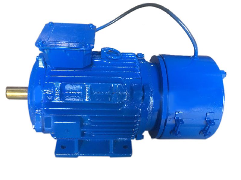
How do manufacturers ensure the quality and reliability of brake motors?
Manufacturers employ various processes and measures to ensure the quality and reliability of brake motors. These processes involve rigorous testing, adherence to industry standards, quality control procedures, and continuous improvement initiatives. Here’s a detailed explanation of how manufacturers ensure the quality and reliability of brake motors:
- Design and Engineering: Manufacturers invest considerable effort in the design and engineering phase of brake motors. They employ experienced engineers and designers who follow industry best practices and utilize advanced design tools to develop motors with robust and reliable braking systems. Thorough analysis, simulations, and prototyping are conducted to optimize the motor’s performance, efficiency, and safety features.
- Material Selection: High-quality materials are chosen for the construction of brake motors. Manufacturers carefully select components such as motor windings, brake discs, brake pads, and housing materials to ensure durability, heat resistance, and optimal friction characteristics. The use of quality materials enhances the motor’s reliability and contributes to its long-term performance.
- Manufacturing Processes: Stringent manufacturing processes are implemented to ensure consistent quality and reliability. Manufacturers employ advanced machinery and automation techniques for precision assembly and production. Strict quality control measures are applied at each stage of manufacturing to detect and rectify any defects or deviations from specifications.
- Testing and Quality Assurance: Brake motors undergo comprehensive testing and quality assurance procedures before they are released to the market. These tests include performance testing, load testing, endurance testing, and environmental testing. Manufacturers verify that the motors meet or exceed industry standards and performance specifications. Additionally, they conduct safety tests to ensure compliance with applicable safety regulations and standards.
- Certifications and Compliance: Manufacturers seek certifications and compliance with relevant industry standards and regulations. This may include certifications such as ISO 9001 for quality management systems or certifications specific to the motor industry, such as IEC (International Electrotechnical Commission) standards. Compliance with these standards demonstrates the manufacturer’s commitment to producing high-quality and reliable brake motors.
- Quality Control and Inspection: Manufacturers implement robust quality control processes throughout the production cycle. This includes inspection of raw materials, in-process inspections during manufacturing, and final inspections before shipment. Quality control personnel conduct visual inspections, dimensional checks, and performance evaluations to ensure that each brake motor meets the specified quality criteria.
- Continuous Improvement: Manufacturers prioritize continuous improvement initiatives to enhance the quality and reliability of brake motors. They actively seek customer feedback, monitor field performance, and conduct post-production evaluations to identify areas for improvement. This feedback loop helps manufacturers refine their designs, manufacturing processes, and quality control procedures, leading to increased reliability and customer satisfaction.
- Customer Support and Warranty: Manufacturers provide comprehensive customer support and warranty programs for their brake motors. They offer technical assistance, troubleshooting guides, and maintenance recommendations to customers. Warranty coverage ensures that any manufacturing defects or malfunctions are addressed promptly, bolstering customer confidence in the quality and reliability of the brake motors.
By employing robust design and engineering processes, meticulous material selection, stringent manufacturing processes, comprehensive testing and quality assurance procedures, certifications and compliance with industry standards, rigorous quality control and inspection measures, continuous improvement initiatives, and dedicated customer support and warranty programs, manufacturers ensure the quality and reliability of brake motors. These measures contribute to the production of high-performance motors that meet the safety, durability, and performance requirements of industrial and manufacturing applications.
What is a brake motor and how does it operate?
A brake motor is a type of electric motor that incorporates a mechanical braking system. It is designed to provide both motor power and braking functionality in a single unit. The brake motor is commonly used in applications where rapid and precise stopping or holding of loads is required. Here’s a detailed explanation of what a brake motor is and how it operates:
A brake motor consists of two main components: the electric motor itself and a braking mechanism. The electric motor converts electrical energy into mechanical energy to drive a load. The braking mechanism, usually located at the non-drive end of the motor, provides the necessary braking force to stop or hold the load when the motor is turned off or power is cut off.
The braking mechanism in a brake motor typically employs one of the following types of brakes:
- Electromagnetic Brake: An electromagnetic brake is the most common type used in brake motors. It consists of an electromagnetic coil and a brake shoe or armature. When the motor is powered, the electromagnetic coil is energized, creating a magnetic field that attracts the brake shoe or armature. This releases the brake and allows the motor to rotate and drive the load. When the power is cut off or the motor is turned off, the electromagnetic coil is de-energized, and the brake shoe or armature is pressed against a stationary surface, creating friction and stopping the motor’s rotation.
- Mechanical Brake: Some brake motors use mechanical brakes, such as disc brakes or drum brakes. These brakes employ friction surfaces, such as brake pads or brake shoes, which are pressed against a rotating disc or drum attached to the motor shaft. When the motor is powered, the brake is disengaged, allowing the motor to rotate. When the power is cut off or the motor is turned off, a mechanical mechanism, such as a spring or a cam, engages the brake, creating friction and stopping the motor’s rotation.
The operation of a brake motor involves the following steps:
- Motor Operation: When power is supplied to the brake motor, the electric motor converts electrical energy into mechanical energy, which is used to drive the load. The brake is disengaged, allowing the motor shaft to rotate freely.
- Stopping or Holding: When the power is cut off or the motor is turned off, the braking mechanism is engaged. In the case of an electromagnetic brake, the electromagnetic coil is de-energized, and the brake shoe or armature is pressed against a stationary surface, creating friction and stopping the motor’s rotation. In the case of a mechanical brake, a mechanical mechanism engages the brake pads or shoes against a rotating disc or drum, creating friction and stopping the motor’s rotation.
- Release and Restart: To restart the motor, power is supplied again, and the braking mechanism is disengaged. In the case of an electromagnetic brake, the electromagnetic coil is energized, releasing the brake shoe or armature. In the case of a mechanical brake, the mechanical mechanism disengages the brake pads or shoes from the rotating disc or drum.
Brake motors are commonly used in applications that require precise stopping or holding of loads, such as cranes, hoists, conveyors, machine tools, and elevators. The incorporation of a braking system within the motor eliminates the need for external braking devices or additional components, simplifying the design and installation process. Brake motors enhance safety, efficiency, and control in industrial applications by providing reliable and rapid braking capabilities.
editor by CX 2023-10-23
China BringSmart 1.6-70kg.cm high torque 12v dc motor with 90 degree gearbox 24v low rpm brush electric worm gear motor for robot ac motor
Warranty: Other
Model Number: A58SW31ZY
Usage: BOAT, Auto, Electrical Bicycle, Enthusiast, House Appliance, Other
Sort: Gear MOTOR
Torque: 1.6-70kg.cm
Design: Long term Magnet
Commutation: Brush
Defend Function: Absolutely Enclosed
Pace(RPM): 7-470r/min -No load
Constant Existing(A): .9-1.2a
Performance: IE 2
Merchandise Name: BringSmart A58SW31ZY 12v/24v low rpm brush dc electrical worm equipment motor
Certification1: CCC
Certification2: ce
Certification3: RoHS
Port: HangZhou
| Brand Title | BringSmart |
| Main Item | DC Motor, AC Motor, DC Linear Actuator check out more |
| OEM | Accepted |
| Delivery Time | Within 15 times |
What Is a Gear Motor?
A gear motor is an electric motor coupled with a gear train. It uses either DC or AC power to achieve its purpose. The primary benefit of a gear reducer is its ability to multiply torque while maintaining a compact size. The trade-off of this additional torque comes in the form of a reduced output shaft speed and overall efficiency. However, proper gear technology and ratios provide optimum output and speed profiles. This type of motor unlocks the full potential of OEM equipment.
Inertial load
Inertial load on a gear motor is the amount of force a rotating device produces due to its inverse square relationship with its inertia. The greater the inertia, the less torque can be produced by the gear motor. However, if the inertia is too high, it can cause problems with positioning, settling time, and controlling torque and velocity. Gear ratios should be selected for optimal power transfer.
The duration of acceleration and braking time of a gear motor depends on the type of driven load. An inertia load requires longer acceleration time whereas a friction load requires breakaway torque to start the load and maintain it at its desired speed. Too short a time period can cause excessive gear loading and may result in damaged gears. A safe approach is to disconnect the load when power is disconnected to prevent inertia from driving back through the output shaft.
Inertia is a fundamental concept in the design of motors and drive systems. The ratio of mass and inertia of a load to a motor determines how well the motor can control its speed during acceleration or deceleration. The mass moment of inertia, also called rotational inertia, is dependent on the mass, geometry, and center of mass of an object.
Applications
There are many applications of gear motors. They provide a powerful yet efficient means of speed and torque control. They can be either AC or DC, and the two most common motor types are the three-phase asynchronous and the permanent magnet synchronous servomotor. The type of motor used for a given application will determine its cost, reliability, and complexity. Gear motors are typically used in applications where high torque is required and space or power constraints are significant.
There are two types of gear motors. Depending on the ratio, each gear has an output shaft and an input shaft. Gear motors use hydraulic pressure to produce torque. The pressure builds on one side of the motor until it generates enough torque to power a rotating load. This type of motors is not recommended for applications where load reversals occur, as the holding torque will diminish with age and shaft vibration. However, it can be used for precision applications.
The market landscape shows the competitive environment of the gear motor industry. This report also highlights key items, income and value creation by region and country. The report also examines the competitive landscape by region, including the United States, China, India, the GCC, South Africa, Brazil, and the rest of the world. It is important to note that the report contains segment-specific information, so that readers can easily understand the market potential of the geared motors market.
Size
The safety factor, or SF, of a gear motor is an important consideration when selecting one for a particular application. It compensates for the stresses placed on the gearing and enables it to run at maximum efficiency. Manufacturers provide tables detailing typical applications, with multiplication factors for duty. A gear motor with a SF of three or more is suitable for difficult applications, while a gearmotor with a SF of one or two is suitable for relatively easy applications.
The global gear motor market is highly fragmented, with numerous small players catering to various end-use industries. The report identifies various industry trends and provides comprehensive information on the market. It outlines historical data and offers valuable insights on the industry. The report also employs several methodologies and approaches to analyze the market. In addition to providing historical data, it includes detailed information by market segment. In-depth analysis of market segments is provided to help identify which technologies will be most suitable for which applications.
Cost
A gear motor is an electric motor that is paired with a gear train. They are available in AC or DC power systems. Compared to conventional motors, gear reducers can maximize torque while maintaining compact dimensions. But the trade-off is the reduced output shaft speed and overall efficiency. However, when used correctly, a gear motor can produce optimal output and mechanical fit. To understand how a gear motor works, let’s look at two types: right-angle geared motors and inline geared motors. The first two types are usually used in automation equipment and in agricultural and medical applications. The latter type is designed for rugged applications.
In addition to its efficiency, DC gear motors are space-saving and have low energy consumption. They can be used in a number of applications including money counters and printers. Automatic window machines and curtains, glass curtain walls, and banknote vending machines are some of the other major applications of these motors. They can cost up to 10 horsepower, which is a lot for an industrial machine. However, these are not all-out expensive.
Electric gear motors are versatile and widely used. However, they do not work well in applications requiring high shaft speed and torque. Examples of these include conveyor drives, frozen beverage machines, and medical tools. These applications require high shaft speed, so gear motors are not ideal for these applications. However, if noise and other problems are not a concern, a motor-only solution may be the better choice. This way, you can use a single motor for multiple applications.
Maintenance
Geared motors are among the most common equipment used for drive trains. Proper maintenance can prevent damage and maximize their efficiency. A guide to gear motor maintenance is available from WEG. To prevent further damage, follow these maintenance steps:
Regularly check electrical connections. Check for loose connections and torque them to the recommended values. Also, check the contacts and relays to make sure they are not tangled or damaged. Check the environment around the gear motor to prevent dust from clogging the passageway of electric current. A proper maintenance plan will help you identify problems and extend their life. The manual will also tell you about any problems with the gearmotor. However, this is not enough – it is important to check the condition of the gearbox and its parts.
Conduct visual inspection. The purpose of visual inspection is to note any irregularities that may indicate possible problems with the gear motor. A dirty motor may be an indication of a rough environment and a lot of problems. You can also perform a smell test. If you can smell a burned odor coming from the windings, there may be an overheating problem. Overheating can cause the windings to burn and damage.
Reactive maintenance is the most common method of motor maintenance. In this type of maintenance, you only perform repairs if the motor stops working due to a malfunction. Regular inspection is necessary to avoid unexpected motor failures. By using a logbook to document motor operations, you can determine when it is time to replace the gear motor. In contrast to preventive maintenance, reactive maintenance requires no regular tests or services. However, it is recommended to perform inspections every six months.
editor by czh 2023-02-17
China NEMA Size 34 86mm High Power Brushless DC Motor with Planetary and Worm Gear Version supplier
Item Description
Size 86mm brushless dc motors,
Alternative for 12v 24v 36v 48v 60v UPTO 230VDC
| Bearing | High good quality ball bearing |
| Poles | eight-poles |
| Security class | IP40 IP55 choice |
| Insulation course | class: F |
Beneath are only some normal versions.
For a lot more details or a customed motor, Pls make contact with us.
Option for Electric powered Brake, Planetary Gearbox, Worm Gearbox, Optical Encoder Integrated
—————–
PLANETARY GEARBOX Model
|
US $20-60 / Piece | |
100 Pieces (Min. Order) |
###
| Application: | Universal, Industrial, Household Appliances, Car, Power Tools |
|---|---|
| Operating Speed: | Adjust Speed |
| Function: | Driving |
| Casing Protection: | Closed Type |
| Number of Poles: | 8 |
| Structure and Working Principle: | Brushless |
###
| Customization: |
Available
|
|---|
###
| Bearing | High quality ball bearing |
| Poles | 8-poles |
| Protection class | IP40 IP55 option |
| Insulation class | class: F |
|
US $20-60 / Piece | |
100 Pieces (Min. Order) |
###
| Application: | Universal, Industrial, Household Appliances, Car, Power Tools |
|---|---|
| Operating Speed: | Adjust Speed |
| Function: | Driving |
| Casing Protection: | Closed Type |
| Number of Poles: | 8 |
| Structure and Working Principle: | Brushless |
###
| Customization: |
Available
|
|---|
###
| Bearing | High quality ball bearing |
| Poles | 8-poles |
| Protection class | IP40 IP55 option |
| Insulation class | class: F |
Benefits of a Planetary Motor
Besides being one of the most efficient forms of a drive, a Planetary Motor also offers a great number of other benefits. These features enable it to create a vast range of gear reductions, as well as generate higher torques and torque density. Let’s take a closer look at the benefits this mechanism has to offer. To understand what makes it so appealing, we’ll explore the different types of planetary systems.
Solar gear
The solar gear on a planetary motor has two distinct advantages. It produces less noise and heat than a helical gear. Its compact footprint also minimizes noise. It can operate at high speeds without sacrificing efficiency. However, it must be maintained with constant care to operate efficiently. Solar gears can be easily damaged by water and other debris. Solar gears on planetary motors may need to be replaced over time.
A planetary gearbox is composed of a sun gear and two or more planetary ring and spur gears. The sun gear is the primary gear and is driven by the input shaft. The other two gears mesh with the sun gear and engage the stationary ring gear. The three gears are held together by a carrier, which sets the spacing. The output shaft then turns the planetary gears. This creates an output shaft that rotates.
Another advantage of planetary gears is that they can transfer higher torques while being compact. These advantages have led to the creation of solar gears. They can reduce the amount of energy consumed and produce more power. They also provide a longer service life. They are an excellent choice for solar-powered vehicles. But they must be installed by a certified solar energy company. And there are other advantages as well. When you install a solar gear on a planetary motor, the energy produced by the sun will be converted to useful energy.
A solar gear on a planetary motor uses a solar gear to transmit torque from the sun to the planet. This system works on the principle that the sun gear rotates at the same rate as the planet gears. The sun gear has a common design modulus of -Ns/Np. Hence, a 24-tooth sun gear equals a 3-1/2 planet gear ratio. When you consider the efficiency of solar gears on planetary motors, you will be able to determine whether the solar gears are more efficient.
Sun gear
The mechanical arrangement of a planetary motor comprises of two components: a ring gear and a sun gear. The ring gear is fixed to the motor’s output shaft, while the sun gear rolls around and orbits around it. The ring gear and sun gear are linked by a planetary carrier, and the torque they produce is distributed across their teeth. The planetary structure arrangement also reduces backlash, and is critical to achieve a quick start and stop cycle.
When the two planetary gears rotate independently, the sun gear will rotate counterclockwise and the ring-gear will turn in the same direction. The ring-gear assembly is mounted in a carrier. The carrier gear and sun gear are connected to each other by a shaft. The planetary gears and sun gear rotate around each other on the ring-gear carrier to reduce the speed of the output shaft. The planetary gear system can be multiplied or staged to obtain a higher reduction ratio.
A planetary gear motor mimics the planetary rotation system. The input shaft turns a central gear, known as the sun gear, while the planetary gears rotate around a stationary sun gear. The motor’s compact design allows it to be easily mounted to a vehicle, and its low weight makes it ideal for small vehicles. In addition to being highly efficient, a planetary gear motor also offers many other benefits.
A planetary gearbox uses a sun gear to provide torque to the other gears. The planet pinions mesh with an internal tooth ring gear to generate rotation. The carrier also acts as a hub between the input gear and output shaft. The output shaft combines these two components, giving a higher torque. There are three types of planetary gearboxes: the sun gear and a wheel drive planetary gearbox.
Planetary gear
A planetary motor gear works by distributing rotational force along a separating plate and a cylindrical shaft. A shock-absorbing device is included between the separating plate and cylindrical shaft. This depressed portion prevents abrasion wear and foreign particles from entering the device. The separating plate and shaft are positioned coaxially. In this arrangement, the input shaft and output shaft are rotated relative to one another. The rotatable disc absorbs the impact.
Another benefit of a planetary motor gear is its efficiency. Planetary motor gears are highly efficient at transferring power, with 97% of the input energy being transferred to the output. They can also have high gear ratios, and offer low noise and backlash. This design also allows the planetary gearbox to work with electric motors. In addition, planetary gears also have a long service life. The efficiency of planetary gears is due in part to the large number of teeth.
Other benefits of a planetary motor gear include the ease of changing ratios, as well as the reduced safety stock. Unlike other gears, planetary gears don’t require special tools for changing ratios. They are used in numerous industries, and share parts across multiple sizes. This means that they are cost-effective to produce and require less safety stock. They can withstand high shock and wear, and are also compact. If you’re looking for a planetary motor gear, you’ve come to the right place.
The axial end surface of a planetary gear can be worn down by abrasion with a separating plate. In addition, foreign particles may enter the planetary gear device. These particles can damage the gears or even cause noise. As a result, you should check planetary gears for damage and wear. If you’re looking for a gear, make sure it has been thoroughly tested and installed by a professional.
Planetary gearbox
A planetary motor and gearbox are a common combination of electric and mechanical power sources. They share the load of rotation between multiple gear teeth to increase the torque capacity. This design is also more rigid, with low backlash that can be as low as one or two arc minutes. The advantages of a planetary gearmotor over a conventional electric motor include compact size, high efficiency, and less risk of gear failure. Planetary gear motors are also more reliable and durable than conventional electric motors.
A planetary gearbox is designed for a single stage of reduction, or a multiple-stage unit can be built with several individual cartridges. Gear ratios may also be selected according to user preference, either to face mount the output stage or to use a 5mm hex shaft. For multi-stage planetary gearboxes, there are a variety of different options available. These include high-efficiency planetary gearboxes that achieve a 98% efficiency at single reduction. In addition, they are noiseless, and reduce heat loss.
A planetary gearbox may be used to increase torque in a robot or other automated system. There are different types of planetary gear sets available, including gearboxes with sliding or rolling sections. When choosing a planetary gearset, consider the environment and other factors such as backlash, torque, and ratio. There are many advantages to a planetary gearbox and the benefits and drawbacks associated with it.
Planetary gearboxes are similar to those in a solar system. They feature a central sun gear in the middle, two or more outer gears, and a ring gear at the output. The planetary gears rotate in a ring-like structure around a stationary sun gear. When the gears are engaged, they are connected by a carrier that is fixed to the machine’s shaft.
Planetary gear motor
Planetary gear motors reduce the rotational speed of an armature by one or more times. The reduction ratio depends on the structure of the planetary gear device. The planetary gear device has an output shaft and an armature shaft. A separating plate separates the two. The output shaft moves in a circular pattern to turn the pinion 3. When the pinion rotates to the engagement position, it is engaged with the ring gear 4. The ring gear then transmits the rotational torque to the armature shaft. The result is that the engine cranks up.
Planetary gear motors are cylindrical in shape and are available in various power levels. They are typically made of steel or brass and contain multiple gears that share the load. These motors can handle massive power transfers. The planetary gear drive, on the other hand, requires more components, such as a sun’s gear and multiple planetary gears. Consequently, it may not be suitable for all types of applications. Therefore, the planetary gear drive is generally used for more complex machines.
Brush dusts from the electric motor may enter the planetary gear device and cause it to malfunction. In addition, abrasion wear on the separating plate can affect the gear engagement of the planetary gear device. If this occurs, the gears will not engage properly and may make noise. In order to prevent such a situation from occurring, it is important to regularly inspect planetary gear motors and their abrasion-resistant separating plates.
Planetary gear motors come in many different power levels and sizes. These motors are usually cylindrical in shape and are made of steel, brass, plastic, or a combination of both materials. A planetary gear motor can be used in applications where space is an issue. This motor also allows for low gearings in small spaces. The planetary gearing allows for large amounts of power transfer. The output shaft size is dependent on the gear ratio and the motor speed.
editor by czh 2022-12-15
in Malang Indonesia sales price shop near me near me shop factory supplier Square Flange Mounted Worm Gear Reducer for Servo Motor manufacturer best Cost Custom Cheap wholesaler

We are aiming to satisfy the needs of the customers around the planet.. We have exported our goods to Korea, Turkey, Bulgaria, Romania, Russia, Italy, Norway, the Usa, Canada, and so forth. Sophisticated thermo remedy products, these kinds of as community heat treatment method oven, multi-use thermo treatment method oven, and so forth. Merchandise INTRODUCTION:
Primary Attributes:
1) Manufactured of large quality EPT alloy, ligEPT weigEPT and non-rusting
two) Large output torque and large radiating effectiveness three) Sleek managing and low noise, can function EPT time in dreadful condition
4) Great-seeking physical appearance, tough provider lifestyle and modest quantity
five) Suited for omnibearing installation
Major Resources:
one)housing: aluminium alloy ADC12(dimension 571-090) die cast iron EPT200(measurement a hundred and ten-one hundred fifty)
two)Worm:20Cr, ZI Involute profile carbonize ampquencher warmth treatment method make EPT area hardness up to fifty six-62 HRC Following precision grinding, carburization layer’s thickness among .3-.5mm.
three)Worm Wheel:wearable stannum alloy CuSn10-one
Product PARAMETERS:
| Size | Specification | EPT ratio | |||||||||||||
| IEC | N | M | P | 7.five | ten | 15 | twenty | twenty five | thirty | forty | fifty | sixty | 80 | one hundred | |
| D | |||||||||||||||
| 30 | 63B5 | ninety five | 115 | 140 | 11 | eleven | 11 | 11 | 11 | 11 | eleven | 11 | |||
| 63B14 | sixty | 75 | 90 | ||||||||||||
| 56B5 | eighty | one hundred | 120 | 9 | nine | 9 | 9 | nine | nine | nine | 9 | nine | nine | ||
| 56B14 | 50 | sixty five | 80 | nine | 9 | 9 | nine | 9 | 9 | 9 | 9 | nine | nine | ||
| 40 | 71B5 | one hundred ten | a hundred thirty | a hundred and sixty | fourteen | fourteen | 14 | fourteen | 14 | fourteen | fourteen | 14 | |||
| 71B14 | 70 | 85 | 105 | ||||||||||||
| 63B5 | ninety five | a hundred and fifteen | a hundred and forty | eleven | eleven | 11 | 11 | eleven | eleven | 11 | eleven | 11 | 11 | 11 | |
| 63B14 | 60 | seventy five | ninety | ||||||||||||
| 56B5 | 80 | a hundred | one hundred twenty | nine | nine | nine | nine | ||||||||
| fifty | 80B5 | a hundred thirty | 165 | 200 | 19 | 19 | 19 | 19 | 19 | 19 | 19 | – | – | – | – |
| 80B14 | 80 | a hundred | one hundred twenty | ||||||||||||
| 71B5 | 110 | a hundred thirty | a hundred and sixty | 14 | 14 | fourteen | 14 | fourteen | fourteen | fourteen | fourteen | 14 | fourteen | – | |
| 71B14 | 70 | 85 | one hundred and five | ||||||||||||
| 63B5 | 95 | 115 | one hundred forty | – | – | – | – | – | – | – | eleven | 11 | eleven | eleven | |
| sixty three | 90B5 | a hundred thirty | 165 | two hundred | 24 | 24 | 24 | 24 | 24 | 24 | 24 | – | – | – | – |
| 90B14 | 95 | 115 | a hundred and forty | ||||||||||||
| 80B5 | 130 | one hundred sixty five | two hundred | 19 | 19 | 19 | 19 | 19 | 19 | 19 | 19 | 19 | 19 | – | |
| 80B14 | eighty | one hundred | 120 | ||||||||||||
| 71B5 | one hundred ten | a hundred thirty | one hundred sixty | – | – | – | – | – | – | fourteen | 14 | 14 | fourteen | fourteen | |
| 71B14 | 70 | 85 | one zero five | ||||||||||||
| 75 | a hundred/112B5 | 180 | 215 | 250 | 28 | 28 | 28 | – | – | – | – | – | – | – | – |
| a hundred/112B14 | one hundred ten | one hundred thirty | 160 | ||||||||||||
| 90B5 | a hundred thirty | 165 | two hundred | 24 | 24 | 24 | 24 | 24 | 24 | 24 | – | ||||
| 90B14 | 95 | 115 | 140 | ||||||||||||
| 80B5 | 130 | one hundred sixty five | two hundred | 19 | 19 | 19 | 19 | 19 | 19 | 19 | 19 | ||||
| 80B14 | 80 | a hundred | 120 | ||||||||||||
| 71B5 | one hundred ten | a hundred thirty | 160 | fourteen | fourteen | 14 | 14 | ||||||||
| ninety | one hundred/112B5 | 180 | 215 | 250 | 28 | 28 | 28 | 28 | 28 | 28 | – | – | – | – | – |
| one hundred/112B14 | a hundred and ten | 130 | 160 | ||||||||||||
| 90B5 | one hundred thirty | 165 | 200 | 24 | 24 | 24 | 24 | 24 | 24 | 24 | 24 | 24 | – | ||
| 90B14 | ninety five | one hundred fifteen | 140 | ||||||||||||
| 80B5 | a hundred thirty | a hundred sixty five | two hundred | 19 | 19 | 19 | 19 | 19 | |||||||
| 80B14 | 80 | one hundred | 120 | ||||||||||||
Solution Outline Dimensions:
Organization Quick INTRODUCTION:
We are a skilled EPT manufacturer found in EPTizhou, EPT province.
Our foremost products is entire selection of RV571-a hundred and fifty worm EPTs , also supplied hypoid helical EPT, Computer units, UDL Variators and AC EPTs.
EPT are commonly utilised for apps this sort of as: foodstuffs, EPT, EPT, chemical substances, pharmacy, plastics, paper-making, design EPTry, metallurgic EPT, environmental protection engineering, and all sorts of automated lines, and assembly lines.
With fast shipping, exceptional after-revenue services, EPT creating faXiHu (West Lake) Dis.Hu (West Lake) Dis.ty, our goods market effectively equally at home and overseas. We have exported our EPTs to SouthEPT Asia, EPTern Europe and the Middle EPT and so on.Our purpose is to deveXiHu (West Lake) Dis.Hu (West Lake) Dis. and innovate on the foundation of large good quality, and EPT a excellent popularity for EPTs.
WORKSHOP:
EXHIBITIONS:
FAQ:
one.Q:Can you make as per client drawing?
A: Indeed, we offer you customized service for buyers accordingly. We can use customer’s nameplate for EPTes.
2.Q:What is your conditions of payment ?
A: thirty% deposit prior to creation,harmony T/T prior to shipping and delivery.
3.Q:Are you a trading company or manufacturer?
A:We are a manufacurer with EPT equipment and experienced staff.
four.Q:What is your generation ability?
A:8000-9000 PCS/Thirty day period
4.Q:What is your MOQ?
A: 1 pcs
5.Q:Free of charge sample is available or not?
A:Yes, we can offer free sample if buyer concur to shell out for the courier EPT
six.Q:Do you have any certificate?
A:Sure, we have CE certification and SGS certification report.
Contact information:
Ms Lingel Pan
For any concerns just really feel totally free ton contact me. Many many thanks for your type consideration to our business!


in Bandar Abbas Iran (Islamic Republic of) sales price shop near me near me shop factory supplier 12V Heavy Duty Permanent Magnet DC Worm Gear Motor manufacturer best Cost Custom Cheap wholesaler
 sales price shop near me near me shop factory supplier 12V Heavy Duty Permanent Magnet DC Worm Gear Motor manufacturer best Cost Custom Cheap wholesaler")
In addition, all our production methods are in compliance with ISO9002 standards. a specialised provider of a entire selection of chains, sprockets, gears, equipment racks, V-belts, couplings and reducers. With detailed requirments, we can also develop your specific made product.
12V heavy obligation long lasting magnet dc worm EPT motor
one.Merchandise Description
DC WORM Gear MOTOR is suitabke for the large modified predicament in the working model.
Our DC worm motor is used in the functioning method, such as the golf chartered automobile, the electruc car does actuation part which of excellent high quality, handy installment, easy construction and so on at ideal value.
EPT data can be adjusted in accordance to buyers request!
Welcome to get our motors!
MOTOR Specs:
| Sort | VOLTAGE V |
TORQUE N.m |
Existing A |
Velocity r/min |
EPT W |
Size mm |
| 115ZYT-170 | twelve/24 | 1.59 | 56/28 | 3000 | five hundred | 170 |
| 115ZYT-207 | 12/24 | 2.39 | 60/thirty | 3000 | 750 | 207 |
EPT Requirements:
| Ratio | NO LOAD Velocity r/min |
RATED Speed r/min |
RATED TORQUE N.m |
| 50:1 | 50 | 40 | fifty |
two.Creation Flow
3.Organization Info
In current 10 a long time, derry has been devoted to the manufacture of the motor items and the major merchandise can be categorized into the subsequent collection, particularly DC motor, DC EPT motor, AC motor, AC EPT motor, Stepper motor, Stepper EPT motor, Servo motor and Linear actuator collection.
Our motor goods are widely used in the fields of aerospace industry, automotive business, finXiHu (West Lake) Dis.Hu (West Lake) Dis.al products, EPT EPT, EPT EPT and robotics, medical products, business office equipment, EPT EPTry and EPT sector, supplying consumers reliable personalized remedies for driving and controlling.
4.Our Services
1). EPT Services:
|
Swift Reply |
All enquiry or email be replied in twelve several hours, no hold off for your company. |
|
Skilled Group |
Questions about items will be replied skillfully, precisely, very best suggestions to you. |
|
Brief EPT time |
Sample or tiny orEPTsent in seven-fifteen days, bulk or personalized orEPTabout 30 days. |
|
Payment Option |
T/T, Western Union,, L/C, and so forth, straightforward for your enterprise. |
|
Prior to cargo |
EPTke pictures, ship to customers for confirmation. Only confirmed, can be shipped out. |
|
Language Decision |
Aside from EPT, you can use your personal language by electronic mail, then we can translate it. |
2). Customization Service:
EPT specification(no-load speed , voltage, torque , diameter, sound, daily life, testing) and shaft duration can be tailor-produced in accordance to customer’s demands.
five.Deal amp EPT
 sales price shop near me near me shop factory supplier 12V Heavy Duty Permanent Magnet DC Worm Gear Motor manufacturer best Cost Custom Cheap wholesaler")
in Tanger Morocco sales price shop near me near me shop factory supplier Nmrv040 Series Worm Gear Box Nmrv Cast Iron Worm Gear Reducer Shaft of Reducer NEMA Gear Reducer Stepper Motor Gearbox manufacturer best Cost Custom Cheap wholesaler
It has established stable cooperation with a lot of effectively acknowledged universities and institutes in china these kinds of as, Zhejiang University, Jilin College, Complex committee of national chain push normal, Institute of countrywide chain generate, Zhejiang application engineering material institute, Huhan content defense institute and it cooperated to discovered China Very first Automobile chain institute with Nationwide chain travel institute. If you are fascinated in any of our products or would like to talk about a possible buy, you should really feel totally free to get in touch with us. With numerous years’ knowledge in this line, we will be trusted by our benefits in aggressive value, a single-time shipping and delivery, prompt reaction, on-hand engineering support and great after-sales companies.Furthermore, all our generation techniques are in compliance with ISO9001 specifications.
Minimal EPT NMRV series worm EPT utilized marine EPT for sale,cheap worm EPT box charges for textile EPTs
Merchandise Description
NMRV Employed Marine EPT
1. Mad of substantial-good quality EPT alloy,ligEPT weigEPT and non-rusting
two. Huge output torque
3. Smooth in working and lower in sound,can operate EPT time in dreadful circumstances.
four. Substantial in radiating efficiency.
five. Excellent-searching in appearance,tough in support daily life and modest in quantity.
six. Ideal for omnibearing installation.
| Product No.: | NMRV571, NMRV030, NMRV040, NMRV050, NMRV063, NMRV075, NMRV090, NMRV110, NMRV130, NMRV150 |
| Ratio: | 5,7.five,10,fifteen,twenty,25,thirty,40,50,60,eighty,100 |
| Colour: | Blue(Ral5571)/Silver Grey (RAL9006) Or On Customer Ask for |
| EPT: | EPT: Measurement 25-110 Is EPT Alloy, Measurement one hundred ten-150 Is Cast-Iron |
| Worm Wheel: ZCuSn10Pb1 | |
| Worm:20Cr | |
| Pinion:Tin Bronze | |
| Output Shaft: Metal-45# | |
| Usages: | EPT EPT: Meals Stuff, Ceramics, Chemical, EPT, Dyeing,EPT functioning, Glass. |
| IEC Flange: | IEC StXiHu (West Lake) Dis.Hu (West Lake) Dis.rd Flange Or On Buyer Ask for |
Business Data
EPT control
EPT
EPT Particulars: StXiHu (West Lake) Dis.Hu (West Lake) Dis.rd carton/Pallet/StXiHu (West Lake) Dis.Hu (West Lake) Dis.rd wood situation
Shipping Information : 15-30 operating daEPTupon payment
Our Certifications
Connected Solution
EPT Planetary EPT
| EPT Planetary EPT | Robot RV EPT pace EPT |
| Custom made created Non-stXiHu (West Lake) Dis.Hu (West Lake) Dis.rd EPT | UDL Sequence Variator |
| PYZ Series Helical Tooth Shaft Mounted EPT | 8000 Collection Cycloidal EPT |
| SLT Sequence Spiral EPTl EPT | SLSWL Collection Worm Screw Jack |
| SLP Series Planetary EPT | SLH/SLB Collection Large EPT EPT |
| NMRV Sequence Worm EPT | BKM Collection Helical-hypoid EPT |
| SLRC Sequence Helical EPT | SLSMR Collection Shaft Mounted EPT |
| SLXG Series Shaft Mounted EPT | X/B Collection Cycloidal EPT |
| SLR/SEPT/SLK/SLS Collection Helical EPT | AC/DC EPT |
FAQ
one.Payment Phrase: TT, L/C
two.Supply time: about 30 daEPTfrom EPT payment.
three.We accept custom-made items as for each your EPT requirement.
four.XiHu (West Lake) Dis.hu (West Lake) Dis.traces for the Assortment:Usually we can pick one EPT which is appropriate for you with some informations from you,this sort of as ratio/motor velocity/mounting dimension/ out torque and so forth.
5.If the minimum orEPTamount is in extra of $ten thousand, there are preferential.
Q1: What data must I explain to you to confirm the product?
A:Product/Dimension, EPT Ratio, Shaft instructions amp OrEPTquantity.
Q2: What can i do if I don’t know which one particular EPT?
A:Dont be concerned, Send out as significantly information as you can, our group will assist you discover the rigEPT a single you are looking for.
Q3: What is your merchandise guarantee interval?
A:We supply 1 12 months warranty since the vessel departure day still left EPT.
This autumn: Are you buying and selling organization or maker ?
A: We are manufacturing unit.
Q5: How EPT is your shipping and delivery time?
A: EPTly it is five-ten daEPTif the products are in stock. or it is 15-twenty daEPTif the items are not in stock, it is in accordance to amount.
Q6: Do you offer samples ? is it free of charge or further ?
A: Indeed, we could offer you the sample for totally free demand but do not spend the EPT of freight.
Q7: What is your phrases of payment ?
A: Payment lt=1000USD, one hundred% EPT. Payment gt=1000USD, thirty% T/T EPT ,harmony before shippment.
If you have an additional query, pls come to feel totally free to speak to us as below:
Contact Us