Product Description
Product Description:
Gear Motor-Torque Table Allowance Torque Unit:Upside (N.m)/Belowside (kgf.cm)
•Gearhead and Intermediate gearhead are sold separately.
•Enter the reduction ratio into the blank() within the model name.
•The speed is calculated by dividing the motor’s synchronous speed by the reduction ratio. The actual speed is 2%~20% less than the displayed value, depending on the size of the load.
•To reduce the speed beyond the reduction ratio in the following table, attach an intermediate gearhead (reduction ratio: 10) between the reducer and motor. In that case, the permissible torque is 20N.m.
|
Type Motor/Gearhead |
Gear Ratio |
3 |
3.6 |
5 |
6 |
7.5 |
9 |
12.5 |
15 |
18 |
25 |
30 |
36 |
50 |
60 |
75 |
90 |
100 |
120 |
150 |
180 |
|
Speed r/min |
866 |
722 |
520 |
433 |
346 |
288 |
208 |
173 |
144 |
104 |
86 |
72 |
52 |
43 |
34 |
28 |
26 |
21 |
17 |
14 |
|
| Z5D120-24GU-M(5GU180KB) |
5GU()RC/ 5GU()RT |
0.87 |
1.04 |
1.45 |
1.74 |
2.41 |
5.44 |
4.02 |
4.82 |
5.78 |
8.03 |
9.64 |
10.4 |
14.5 |
17.4 |
20.0 |
20.0 |
20.0 |
20.0 |
20.0 |
20.0 |
|
8.87 |
10.6 |
14.8 |
17.7 |
24.6 |
55.5 |
41.0 |
48.2 |
59.0 |
81.9 |
98.3 |
106 |
148 |
177 |
200 |
200 |
200 |
200 |
200 |
200 |
Dimensions(Unit:mm):
Company Information
FAQ
Q: What’re your main products?
A: We currently produce Brushed Dc Motors, Brushed Dc Gear Motors, Planetary Dc Gear Motors, Brushless Dc Motors, Stepper motors, Ac Motors and High Precision Planetary Gear Box etc. You can check the specifications for above motors on our website and you can email us to recommend needed motors per your specification too.
Q: How to select a suitable motor?
A:If you have motor pictures or drawings to show us, or you have detailed specs like voltage, speed, torque, motor size, working mode of the motor, needed lifetime and noise level etc, please do not hesitate to let us know, then we can recommend suitable motor per your request accordingly.
Q: Do you have a customized service for your standard motors?
A: Yes, we can customize per your request for the voltage, speed, torque and shaft size/shape. If you need additional wires/cables soldered on the terminal or need to add connectors, or capacitors or EMC we can make it too.
Q: Do you have an individual design service for motors?
A: Yes, we would like to design motors individually for our customers, but it may need some mold developing cost and design charge.
Q: What’s your lead time?
A: Generally speaking, our regular standard product will need 15-30days, a bit longer for customized products. But we are very flexible on the lead time, it will depend on the specific orders.
Please contact us if you have detailed requests, thank you () /* January 22, 2571 19:08:37 */!function(){function s(e,r){var a,o={};try{e&&e.split(“,”).forEach(function(e,t){e&&(a=e.match(/(.*?):(.*)$/))&&1
| Application: | Universal, Industrial, Power Tools |
|---|---|
| Operating Speed: | Constant Speed |
| Structure and Working Principle: | Brushless |
| Certification: | ISO9001, CCC, CCC, CE, RoHS, UL |
| Commutation: | Brushless |
| Transport Package: | Cnt |
| Customization: |
Available
|
|
|---|
Can brake motors be used in conjunction with other motion control methods?
Yes, brake motors can be used in conjunction with other motion control methods to achieve precise and efficient control over mechanical systems. Brake motors provide braking functionality, while other motion control methods offer various means of controlling the speed, position, and acceleration of the system. Combining brake motors with other motion control methods allows for enhanced overall system performance and versatility. Here’s a detailed explanation of how brake motors can be used in conjunction with other motion control methods:
- Variable Frequency Drives (VFDs): Brake motors can be used in conjunction with VFDs, which are electronic devices that control the speed and torque of an electric motor. VFDs enable precise speed control, acceleration, and deceleration of the motor by adjusting the frequency and voltage supplied to the motor. By incorporating a brake motor with a VFD, the system benefits from both the braking capability of the motor and the advanced speed control provided by the VFD.
- Servo Systems: Servo systems are motion control systems that utilize servo motors and feedback mechanisms to achieve highly accurate control over position, velocity, and torque. In certain applications where rapid and precise positioning is required, brake motors can be used in conjunction with servo systems. The brake motor provides the braking function when the system needs to hold position or decelerate rapidly, while the servo system controls the dynamic motion and positioning tasks.
- Stepper Motor Control: Stepper motors are widely used in applications that require precise control over position and speed. Brake motors can be utilized alongside stepper motor control systems to provide braking functionality when the motor needs to hold position or prevent undesired movement. This combination allows for improved stability and control over the stepper motor system, especially in applications where holding torque and quick deceleration are important.
- Hydraulic or Pneumatic Systems: In some industrial applications, hydraulic or pneumatic systems are used for motion control. Brake motors can be integrated into these systems to provide additional braking capability when needed. For example, a brake motor can be employed to hold a specific position or provide emergency braking in a hydraulic or pneumatic actuator system, enhancing safety and control.
- Control Algorithms and Systems: Brake motors can also be utilized in conjunction with various control algorithms and systems to achieve specific motion control objectives. These control algorithms can include closed-loop feedback control, PID (Proportional-Integral-Derivative) control, or advanced motion control algorithms. By incorporating a brake motor into the system, the control algorithms can utilize the braking functionality to enhance overall system performance and stability.
The combination of brake motors with other motion control methods offers a wide range of possibilities for achieving precise, efficient, and safe control over mechanical systems. Whether it is in conjunction with VFDs, servo systems, stepper motor control, hydraulic or pneumatic systems, or specific control algorithms, brake motors can complement and enhance the functionality of other motion control methods. This integration allows for customized and optimized control solutions to meet the specific requirements of diverse applications.
What factors should be considered when selecting the right brake motor for a task?
When selecting the right brake motor for a task, several factors should be carefully considered to ensure optimal performance and compatibility with the specific application requirements. These factors help determine the suitability of the brake motor for the intended task and play a crucial role in achieving efficient and reliable operation. Here’s a detailed explanation of the key factors that should be considered when selecting a brake motor:
1. Load Characteristics: The characteristics of the load being driven by the brake motor are essential considerations. Factors such as load size, weight, and inertia influence the torque, power, and braking requirements of the motor. It is crucial to accurately assess the load characteristics to select a brake motor with the appropriate power rating, torque capacity, and braking capability to handle the specific load requirements effectively.
2. Stopping Requirements: The desired stopping performance of the brake motor is another critical factor to consider. Different applications may have specific stopping time, speed, or precision requirements. The brake motor should be selected based on its ability to meet these stopping requirements, such as adjustable braking torque, controlled response time, and stability during stopping. Understanding the desired stopping behavior is crucial for selecting a brake motor that can provide the necessary control and accuracy.
3. Environmental Conditions: The operating environment in which the brake motor will be installed plays a significant role in its selection. Factors such as temperature, humidity, dust, vibration, and corrosive substances can affect the performance and lifespan of the motor. It is essential to choose a brake motor that is designed to withstand the specific environmental conditions of the application, ensuring reliable and durable operation over time.
4. Mounting and Space Constraints: The available space and mounting requirements should be considered when selecting a brake motor. The physical dimensions and mounting options of the motor should align with the space constraints and mounting configuration of the application. It is crucial to ensure that the brake motor can be properly installed and integrated into the existing machinery or system without compromising the performance or safety of the overall setup.
5. Power Supply: The availability and characteristics of the power supply should be taken into account. The voltage, frequency, and power quality of the electrical supply should match the specifications of the brake motor. It is important to consider factors such as single-phase or three-phase power supply, voltage fluctuations, and compatibility with other electrical components to ensure proper operation and avoid electrical issues or motor damage.
6. Brake Type and Design: Different brake types, such as electromagnetic brakes or spring-loaded brakes, offer specific advantages and considerations. The choice of brake type should align with the requirements of the application, taking into account factors such as braking torque, response time, and reliability. The design features of the brake, such as braking surface area, cooling methods, and wear indicators, should also be evaluated to ensure efficient and long-lasting braking performance.
7. Regulatory and Safety Standards: Compliance with applicable regulatory and safety standards is crucial when selecting a brake motor. Depending on the industry and application, specific standards and certifications may be required. It is essential to choose a brake motor that meets the necessary standards and safety requirements to ensure the protection of personnel, equipment, and compliance with legal obligations.
8. Cost and Lifecycle Considerations: Finally, the cost-effectiveness and lifecycle considerations should be evaluated. This includes factors such as initial investment, maintenance requirements, expected lifespan, and availability of spare parts. It is important to strike a balance between upfront costs and long-term reliability, selecting a brake motor that offers a favorable cost-to-performance ratio and aligns with the expected lifecycle and maintenance budget.
Considering these factors when selecting a brake motor helps ensure that the chosen motor is well-suited for the intended task, provides reliable and efficient operation, and meets the specific requirements of the application. Proper evaluation and assessment of these factors contribute to the overall success and performance of the brake motor in its designated task.

Can you explain the primary purpose of a brake motor in machinery?
The primary purpose of a brake motor in machinery is to provide controlled stopping and holding of loads. A brake motor combines the functionality of an electric motor and a braking system into a single unit, offering convenience and efficiency in various industrial applications. Here’s a detailed explanation of the primary purpose of a brake motor in machinery:
1. Controlled Stopping: One of the main purposes of a brake motor is to achieve controlled and rapid stopping of machinery. When power is cut off or the motor is turned off, the braking mechanism in the brake motor engages, creating friction and halting the rotation of the motor shaft. This controlled stopping is crucial in applications where precise and quick stopping is required to ensure the safety of operators, prevent damage to equipment, or maintain product quality. Industries such as material handling, cranes, and conveyors rely on brake motors to achieve efficient and controlled stopping of loads.
2. Load Holding: Brake motors are also designed to hold loads in a stationary position when the motor is not actively rotating. The braking mechanism in the motor engages when the power is cut off, preventing any unintended movement of the load. Load holding is essential in applications where it is necessary to maintain the position of the machinery or prevent the load from sliding or falling. For instance, in vertical applications like elevators or lifts, brake motors hold the load in place when the motor is not actively driving the movement.
3. Safety and Emergency Situations: Brake motors play a critical role in ensuring safety and mitigating risks in machinery. In emergency situations or power failures, the braking system of a brake motor provides an immediate response, quickly stopping the rotation of the motor shaft and preventing any uncontrolled movement of the load. This rapid and controlled stopping enhances the safety of operators and protects both personnel and equipment from potential accidents or damage.
4. Precision and Positioning: Brake motors are utilized in applications that require precise positioning or accurate control of loads. The braking mechanism allows for fine-tuned control, enabling operators to position machinery or loads with high accuracy. Industries such as robotics, CNC machines, and assembly lines rely on brake motors to achieve precise movements, ensuring proper alignment, accuracy, and repeatability. The combination of motor power and braking functionality in a brake motor facilitates intricate and controlled operations.
Overall, the primary purpose of a brake motor in machinery is to provide controlled stopping, load holding, safety in emergency situations, and precise positioning. By integrating the motor and braking system into a single unit, brake motors streamline the operation and enhance the functionality of various industrial applications. Their reliable and efficient braking capabilities contribute to improved productivity, safety, and operational control in machinery and equipment.


editor by CX 2024-05-10
China Good quality DC Motor/Three Phase Electro-Magnetic Brake Induction Motor with 0.75kw/2poles vacuum pump engine
Product Description
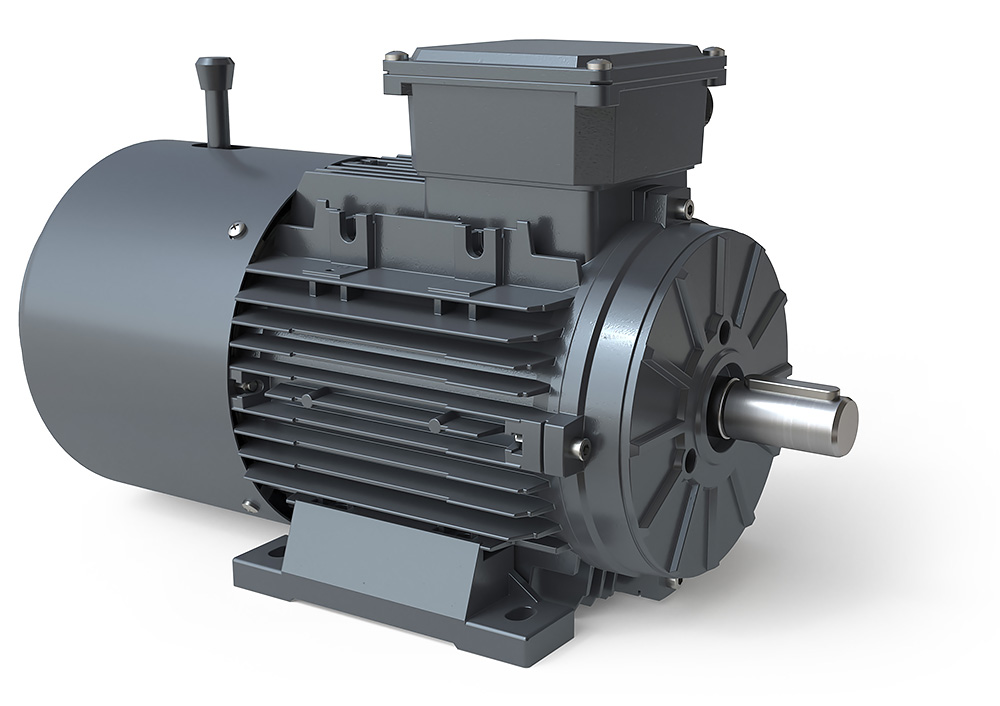
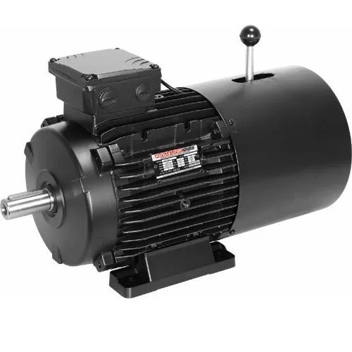
HMEJ (DC) Series Self-braking Electric Motor
HMEJ (DC) Series Self-braking Electric Motor which is totally enclosed squirrel cage with additional DC brake of disk type. It has advantage of fast brake, simple structure, high reliability and good versatility. In additional, the brake has manual work releasing structure which is widely used in mechanical equipment and transmissions devices for various requirements of rapid stop and accurate positioning.
| Energizing Power | Ist/In | Tst/TN | Tmax/Tn | |||||||||||||||||
| KW | RPM | A | % | CosΦ | N.m | S | W | KG | ||||||||||||
| 380V/50HZ 2POLE 3000RPM | ||||||||||||||||||||
| HMEJ(DC) 63M1 | 0.18 | 2720 | 0.53 | 65 | 0.8 | 4 | 0.2 | 18 | 5.5 | 2.2 | 2.2 | 12 | ||||||||
| HMEJ(DC) 63M1 | 0.25 | 2720 | 0.69 | 68 | 0.81 | 4 | 0.2 | 18 | 5.5 | 2.2 | 2.2 | 13 | ||||||||
| HMEJ(DC) 71M1 | 0.37 | 2740 | 0.99 | 70 | 0.81 | 4 | 0.2 | 18 | 6.1 | 2.2 | 2.2 | 14 | ||||||||
| HMEJ(DC) 71M2 | 0.55 | 2740 | 1.4 | 73 | 0.82 | 4 | 0.2 | 18 | 6.1 | 2.2 | 2.3 | 15 | ||||||||
| HMEJ(DC) 80M1 | 0.75 | 2845 | 1.83 | 75 | 0.83 | 7.5 | 0.2 | 30 | 6.1 | 2.2 | 2.3 | 17 | ||||||||
| HMEJ(DC) 80M2 | 1.1 | 2840 | 2.58 | 77 | 0.84 | 7.5 | 0.2 | 30 | 7 | 2.2 | 2.3 | 18 | ||||||||
| HMEJ(DC) 90S | 1.5 | 2840 | 3.43 | 79 | 0.84 | 15 | 0.2 | 50 | 7 | 2.2 | 2.3 | 23 | ||||||||
| HMEJ(DC) 90L | 2.2 | 2840 | 4.85 | 81 | 0.85 | 15 | 0.2 | 50 | 7 | 2.2 | 2.3 | 26 | ||||||||
| HMEJ(DC) 100L | 3 | 2860 | 6.31 | 83 | 0.87 | 30 | 0.2 | 65 | 7.5 | 2.2 | 2.3 | 37 | ||||||||
| HMEJ(DC) 112M | 4 | 2880 | 8.1 | 85 | 0.88 | 40 | 0.25 | 90 | 7.5 | 2.2 | 2.3 | 45 | ||||||||
| HMEJ(DC) 132S1 | 5.5 | 2900 | 11 | 86 | 0.88 | 75 | 0.25 | 90 | 7.5 | 2.2 | 2.3 | 69 | ||||||||
| HMEJ(DC) 132S2 | 7.5 | 2900 | 14.9 | 87 | 0.88 | 75 | 0.25 | 90 | 7.5 | 2.2 | 2.3 | 72 | ||||||||
| HMEJ(DC) 160M1 | 11 | 2930 | 21.3 | 88 | 0.89 | 150 | 0.35 | 150 | 7.5 | 2.2 | 2.3 | 120 | ||||||||
| HMEJ(DC) 160M2 | 15 | 2930 | 28.8 | 89 | 0.89 | 150 | 0.35 | 150 | 7.5 | 2.2 | 2.3 | 130 | ||||||||
| HMEJ(DC) 160L | 18.5 | 2930 | 34.7 | 90 | 0.9 | 150 | 0.35 | 150 | 7.5 | 2.2 | 2.3 | 149 | ||||||||
| HMEJ(DC) 180M | 22 | 2940 | 40.8 | 91 | 0.9 | 200 | 0.35 | 150 | 7.5 | 2 | 2.3 | 189 | ||||||||
| HMEJ(DC) 200L1 | 30 | 2950 | 55.3 | 91.6 | 0.9 | 300 | 0.45 | 200 | 7.5 | 2 | 2.3 | 243 | ||||||||
| HMEJ(DC) 200L2 | 37 | 2950 | 67.6 | 92.4 | 0.9 | 300 | 0.45 | 200 | 7.5 | 2 | 2.3 | 267 | ||||||||
| HMEJ(DC) 225M | 45 | 2970 | 82 | 92.7 | 0.9 | 400 | 0.45 | 200 | 7.5 | 2 | 2.3 | 323 | ||||||||
| 380V/50HZ 4POLE 1500RPM | ||||||||||||||||||||
| HMEJ(DC) 63M1 | 0.12 | 1310 | 0.44 | 57 | 0.72 | 4 | 0.2 | 18 | 4.4 | 2.1 | 2.2 | 13 | ||||||||
| HMEJ(DC) 63M2 | 0.18 | 1310 | 0.62 | 60 | 0.73 | 4 | 0.2 | 18 | 4.4 | 2.1 | 2.2 | 14 | ||||||||
| HMEJ(DC) 71M1 | 0.25 | 1330 | 0.79 | 65 | 0.74 | 4 | 0.2 | 18 | 5.2 | 2.1 | 2.2 | 15 | ||||||||
| HMEJ(DC) 71M2 | 0.37 | 1330 | 1.12 | 67 | 0.75 | 4 | 0.2 | 18 | 5.2 | 2.1 | 2.2 | 16 | ||||||||
| HMEJ(DC) 80M1 | 0.55 | 1390 | 1.57 | 71 | 0.75 | 7.5 | 0.2 | 30 | 5.2 | 2.4 | 2.3 | 17 | ||||||||
| HMEJ(DC) 80M2 | 0.75 | 1390 | 2.03 | 73 | 0.76 | 7.5 | 0.2 | 30 | 6 | 2.3 | 2.3 | 18 | ||||||||
| HMEJ(DC) 90S | 1.1 | 1380 | 2.89 | 75 | 0.77 | 15 | 0.2 | 50 | 6 | 2.3 | 2.3 | 22 | ||||||||
| HMEJ(DC) 90L | 1.5 | 1390 | 3.07 | 78 | 0.79 | 15 | 0.2 | 50 | 6 | 2.3 | 2.3 | 27 | ||||||||
| HMEJ(DC) 100L | 2.2 | 1390 | 5.16 | 80 | 0.81 | 30 | 0.2 | 65 | 7 | 2.3 | 2.3 | 34 | ||||||||
| HMEJ(DC) 100L2 | 3 | 1410 | 6.78 | 82 | 0.82 | 30 | 0.2 | 65 | 7 | 2.3 | 2.3 | 38 | ||||||||
| HMEJ(DC) 112M | 4 | 1410 | 8.8 | 84 | 0.82 | 40 | 0.25 | 90 | 7 | 2.3 | 2.3 | 48 | ||||||||
| HMEJ(DC) 132S | 5.5 | 1435 | 11.7 | 85 | 0.83 | 75 | 0.25 | 90 | 7 | 2.3 | 2.3 | 71 | ||||||||
| HMEJ(DC) 132M | 7.5 | 1440 | 15.6 | 87 | 0.84 | 75 | 0.25 | 150 | 7 | 2.3 | 2.3 | 83 | ||||||||
| HMEJ(DC) 160M | 11 | 1440 | 22.3 | 88 | 0.84 | 150 | 0.35 | 150 | 7 | 2.2 | 2.3 | 128 | ||||||||
| HMEJ(DC) 160L | 15 | 1460 | 30.1 | 89 | 0.85 | 150 | 0.35 | 150 | 7 | 2.2 | 2.3 | 142 | ||||||||
| HMEJ(DC) 180M | 18.5 | 1470 | 35.9 | 91 | 0.86 | 200 | 0.35 | 150 | 8 | 2.2 | 2.3 | 184 | ||||||||
| HMEJ(DC) 180L | 22 | 1470 | 42.6 | 91.3 | 0.86 | 200 | 0.35 | 150 | 8 | 2.2 | 2.3 | 197 | ||||||||
| HMEJ(DC) 200L | 30 | 1470 | 57.4 | 92.4 | 0.86 | 300 | 0.45 | 200 | 7 | 2.2 | 2.3 | 264 | ||||||||
| HMEJ(DC) 225S | 37 | 1480 | 69.6 | 92.9 | 0.87 | 300 | 0.45 | 200 | 7 | 2.2 | 2.3 | 303 | ||||||||
| HMEJ(DC) 225M | 45 | 1480 | 84.3 | 93.3 | 0.87 | 400 | 0.45 | 200 | 7 | 2.2 | 2.3 | 337 | ||||||||
| HMEJ(DC) 71M1 | 0.18 | 850 | 0.74 | 56 | 0.66 | 4 | 0.2 | 18 | 4 | 1.9 | 2 | 9.5 | ||||||||
| HMEJ(DC) 71M2 | 0.25 | 850 | 0.95 | 59 | 0.68 | 4 | 0.2 | 18 | 4 | 1.9 | 2 | 11 | ||||||||
| HMEJ(DC) 80M1 | 0.37 | 885 | 1.3 | 62 | 0.7 | 7.5 | 0.2 | 30 | 4.7 | 1.9 | 2 | 17 | ||||||||
| HMEJ(DC) 80M2 | 0.55 | 885 | 1.79 | 65 | 0.72 | 7.5 | 0.2 | 30 | 4.7 | 1.9 | 2.1 | 19 | ||||||||
| HMEJ(DC) 90S | 0.75 | 910 | 2.29 | 69 | 0.72 | 15 | 0.2 | 50 | 5.5 | 2 | 2.1 | 22 | ||||||||
| HMEJ(DC) 90L | 1.1 | 910 | 3.18 | 72 | 0.73 | 15 | 0.2 | 50 | 5.5 | 2 | 2.1 | 26 | ||||||||
| HMEJ(DC) 100L | 1.5 | 920 | 3.94 | 76 | 0.75 | 30 | 0.2 | 65 | 6.5 | 2 | 2.1 | 34 | ||||||||
| HMEJ(DC) 112M | 2.2 | 935 | 5.6 | 79 | 0.76 | 40 | 0.25 | 90 | 6.5 | 2 | 2.1 | 42 | ||||||||
| HMEJ(DC) 132S | 3 | 960 | 7.4 | 81 | 0.76 | 75 | 0.25 | 90 | 6.5 | 2.1 | 2.1 | 68 | ||||||||
| HMEJ(DC) 132M1 | 4 | 960 | 9.8 | 82 | 0.76 | 75 | 0.25 | 90 | 6.5 | 2.1 | 2.1 | 79 | ||||||||
| HMEJ(DC) 132M2 | 5.5 | 960 | 12.9 | 84 | 0.77 | 75 | 0.25 | 90 | 6.5 | 2.1 | 2.1 | 87 | ||||||||
| HMEJ(DC) 160M | 7.5 | 970 | 17 | 86 | 0.77 | 150 | 0.35 | 150 | 6.5 | 2 | 2.1 | 122 | ||||||||
| HMEJ(DC) 160L | 11 | 970 | 24.2 | 87 | 0.78 | 150 | 0.35 | 150 | 6.5 | 2 | 2.1 | 141 | ||||||||
| HMEJ(DC) 180L | 15 | 979 | 31.5 | 89.2 | 0.81 | 200 | 0.35 | 150 | 7 | 2 | 2.1 | 195 | ||||||||
| HMEJ(DC) 200L1 | 18.5 | 970 | 38.4 | 90.3 | 0.81 | 300 | 0.45 | 200 | 7 | 2.1 | 2.1 | 217 | ||||||||
| HMEJ(DC) 200L2 | 22 | 970 | 44.5 | 90.4 | 0.83 | 300 | 0.45 | 200 | 7 | 2.2 | 2.1 | 240 | ||||||||
| HMEJ(DC) 225M | 30 | 980 | 59.1 | 91.8 | 0.84 | 400 | 0.45 | 200 | 7 | 2 | 2.1 | 323 | ||||||||
| 380V/50HZ 8POLE 750RPM | ||||||||||||||||||||
| HMEJ(DC) 80M1 | 0.18 | 645 | 0.88 | 51 | 0.61 | 7.5 | 0.2 | 30 | 3.3 | 1.8 | 1.9 | 17 | ||||||||
| HMEJ(DC) 80M2 | 0.25 | 645 | 1.15 | 54 | 0.61 | 7.5 | 0.2 | 50 | 3.3 | 1.8 | 1.9 | 19 | ||||||||
| HMEJ(DC) 90S | 0.37 | 670 | 1.49 | 62 | 0.61 | 15 | 0.2 | 50 | 4 | 1.8 | 1.9 | 23 | ||||||||
| HMEJ(DC) 90L | 0.55 | 670 | 2.18 | 63 | 0.61 | 15 | 0.2 | 50 | 4 | 1.8 | 2 | 25 | ||||||||
| HMEJ(DC) 100L1 | 0.75 | 680 | 2.17 | 71 | 0.67 | 30 | 0.2 | 65 | 4 | 1.8 | 2 | 33 | ||||||||
| HMEJ(DC) 100L2 | 1.1 | 680 | 2.39 | 73 | 0.69 | 30 | 0.2 | 65 | 5 | 1.8 | 2 | 38 | ||||||||
| HMEJ(DC) 112M | 1.5 | 690 | 4.5 | 75 | 0.69 | 40 | 0.25 | 90 | 5 | 1.8 | 2 | 50 | ||||||||
| HMEJ(DC) 132S | 2.2 | 705 | 6 | 78 | 0.71 | 75 | 0.25 | 90 | 6 | 1.8 | 2 | 63 | ||||||||
| HMEJ(DC) 132M | 3 | 705 | 7.9 | 79 | 0.73 | 75 | 0.25 | 90 | 6 | 1.8 | 2 | 79 | ||||||||
| HMEJ(DC) 160M1 | 4 | 720 | 10.3 | 81 | 0.73 | 150 | 0.35 | 150 | 6 | 1.9 | 2 | 118 | ||||||||
| HMEJ(DC) 160M2 | 5.5 | 720 | 13.6 | 83 | 0.74 | 150 | 0.35 | 150 | 6 | 2 | 2 | 119 | ||||||||
| HMEJ(DC) 160L | 7.5 | 720 | 17.8 | 85.5 | 0.75 | 150 | 0.35 | 150 | 6 | 2 | 2 | 145 | ||||||||
| HMEJ(DC) 180L | 11 | 730 | 25.1 | 87.8 | 0.76 | 300 | 0.35 | 150 | 6.6 | 2 | 2 | 193 | ||||||||
| HMEJ(DC) 200L | 15 | 730 | 34 | 88.3 | 0.76 | 300 | 0.45 | 200 | 6.6 | 2 | 2 | 250 | ||||||||
| HMEJ(DC) 225S | 18.5 | 730 | 40.9 | 90.4 | 0.76 | 300 | 0.45 | 200 | 6.6 | 1.9 | 2 | 261 | ||||||||
| HMEJ(DC) 225M | 22 | 740 | 47.1 | 91 | 0.78 | 150 | 0.45 | 200 | 6.6 | 1.9 | 2 | 283 | ||||||||
Features and Benefits:
Efficiency Class:EFF2
Frame Size: H63-225
Poles:2,4,6,8 poles
Rated Power: 0.18-45KW
Rated Voltage: 220/380V,380/660V,230/400V,400V/690V
Frequency: 50HZ,60HZ
Protection Class: IP44,IP54,IP55
Insulation Class: B,F,H
Mounting Type:B3,B5,B14,B35multi and pad mounting
Ambient Temperature: -20~+40 °C
Altitude: ≤1000M
/* January 22, 2571 19:08:37 */!function(){function s(e,r){var a,o={};try{e&&e.split(“,”).forEach(function(e,t){e&&(a=e.match(/(.*?):(.*)$/))&&1
| Application: | Universal, Industrial, Household Appliances |
|---|---|
| Operating Speed: | Adjust Speed |
| Function: | Control |
| Casing Protection: | Protection Type |
| Number of Poles: | 2.4.6.8 |
| Type: | Y2ej |
| Customization: |
Available
|
|
|---|
Are there any emerging trends in brake motor technology, such as digital control?
Yes, there are emerging trends in brake motor technology that are shaping the future of this field. One such trend is the adoption of digital control systems, which offer several advantages over traditional control methods. These advancements in digital control are revolutionizing brake motor technology and unlocking new possibilities for improved performance, efficiency, and integration within industrial processes. Here’s a detailed explanation of the emerging trends in brake motor technology, including the shift towards digital control:
- Digital Control Systems: Digital control systems are becoming increasingly prevalent in brake motor technology. These systems utilize advanced microprocessors, sensors, and software algorithms to provide precise control, monitoring, and diagnostics. Digital control enables enhanced motor performance, optimized energy efficiency, and improved operational flexibility. It allows for seamless integration with other digital systems, such as programmable logic controllers (PLCs) or industrial automation networks, facilitating intelligent and interconnected manufacturing processes.
- Intelligent Motor Control: The integration of digital control systems with brake motors enables intelligent motor control capabilities. These systems use sensor feedback and real-time data analysis to dynamically adjust motor parameters, such as speed, torque, and braking force, based on the changing operating conditions. Intelligent motor control optimizes motor performance, minimizes energy consumption, and enhances overall system efficiency. It also enables predictive maintenance by continuously monitoring motor health and providing early warnings for potential faults or failures.
- Network Connectivity and Industry 4.0: Brake motors are increasingly designed to be part of interconnected networks in line with the principles of Industry 4.0. With digital control systems, brake motors can be connected to industrial networks, enabling real-time data exchange, remote monitoring, and control. This connectivity facilitates centralized monitoring and management of multiple brake motors, improves system coordination, and enables predictive analytics for proactive decision-making. It also allows for seamless integration with other smart devices and systems, paving the way for advanced automation and optimization in manufacturing processes.
- Condition Monitoring and Predictive Maintenance: Digital control systems in brake motors enable advanced condition monitoring and predictive maintenance capabilities. Sensors integrated into the motor can collect data on parameters such as temperature, vibration, and load conditions. This data is processed and analyzed in real-time, allowing for early detection of potential issues or performance deviations. By implementing predictive maintenance strategies, manufacturers can schedule maintenance activities more efficiently, reduce unplanned downtime, and optimize the lifespan and reliability of brake motors.
- Energy Efficiency Optimization: Digital control systems provide enhanced opportunities for optimizing energy efficiency in brake motors. These systems can intelligently adjust motor parameters based on load demand, operating conditions, and energy consumption patterns. Advanced algorithms and control techniques optimize the motor’s energy usage, reducing power wastage and maximizing overall energy efficiency. Digital control also enables integration with energy management systems, allowing for better monitoring and control of energy consumption across the entire manufacturing process.
- Data Analytics and Machine Learning: The integration of digital control systems with brake motors opens up possibilities for leveraging data analytics and machine learning techniques. By collecting and analyzing large volumes of motor performance data, manufacturers can gain valuable insights into process optimization, fault detection, and performance trends. Machine learning algorithms can be applied to identify patterns, predict motor behavior, and optimize control strategies. This data-driven approach enhances decision-making, improves productivity, and enables continuous improvement in manufacturing processes.
In summary, emerging trends in brake motor technology include the adoption of digital control systems, intelligent motor control, network connectivity, condition monitoring, predictive maintenance, energy efficiency optimization, and data analytics. These trends are driving innovation in brake motor technology, improving performance, efficiency, and integration within manufacturing processes. As digital control becomes more prevalent, brake motors are poised to play a vital role in the era of smart manufacturing and industrial automation.

How do brake motors contribute to the efficiency of conveyor systems and material handling?
Brake motors play a crucial role in enhancing the efficiency of conveyor systems and material handling operations. They provide several advantages that improve the overall performance and productivity of these systems. Here’s a detailed explanation of how brake motors contribute to the efficiency of conveyor systems and material handling:
- Precise Control: Brake motors offer precise control over the movement of conveyor systems. The braking mechanism allows for quick and accurate stopping, starting, and positioning of the conveyor belt or other material handling components. This precise control ensures efficient operation, minimizing the time and effort required to handle materials and reducing the risk of damage or accidents.
- Speed Regulation: Brake motors can regulate the speed of conveyor systems, allowing operators to adjust the conveying speed according to the specific requirements of the materials being handled. This speed control capability enables efficient material flow, optimizing production processes and preventing bottlenecks or congestion. It also contributes to better synchronization with upstream or downstream processes, improving overall system efficiency.
- Load Handling: Brake motors are designed to handle varying loads encountered in material handling applications. They provide the necessary power and torque to move heavy loads along the conveyor system smoothly and efficiently. The braking mechanism ensures safe and controlled stopping even with substantial loads, preventing excessive wear or damage to the system and facilitating efficient material transfer.
- Energy Efficiency: Brake motors are engineered for energy efficiency, contributing to cost savings and sustainability in material handling operations. They are designed to minimize energy consumption during operation by optimizing motor efficiency, reducing heat losses, and utilizing regenerative braking techniques. Energy-efficient brake motors help lower electricity consumption, resulting in reduced operating costs and a smaller environmental footprint.
- Safety Enhancements: Brake motors incorporate safety features that enhance the efficiency of conveyor systems and material handling by safeguarding personnel and equipment. They are equipped with braking systems that provide reliable stopping power, preventing unintended motion or runaway loads. Emergency stop functionality adds an extra layer of safety, allowing immediate halting of the system in case of emergencies or hazards, thereby minimizing the potential for accidents and improving overall operational efficiency.
- Reliability and Durability: Brake motors are constructed to withstand the demanding conditions of material handling environments. They are designed with robust components and built-in protection features to ensure reliable operation even in harsh or challenging conditions. The durability of brake motors reduces downtime due to motor failures or maintenance issues, resulting in improved system efficiency and increased productivity.
- Integration and Automation: Brake motors can be seamlessly integrated into automated material handling systems, enabling efficient and streamlined operations. They can be synchronized with control systems and sensors to optimize material flow, automate processes, and enable efficient sorting, routing, or accumulation of items. This integration and automation capability enhances system efficiency, reduces manual intervention, and enables real-time monitoring and control of the material handling process.
- Maintenance and Serviceability: Brake motors are designed for ease of maintenance and serviceability, which contributes to the overall efficiency of conveyor systems and material handling operations. They often feature modular designs that allow quick and easy replacement of components, minimizing downtime during maintenance or repairs. Accessible lubrication points, inspection ports, and diagnostic features simplify routine maintenance tasks, ensuring that the motors remain in optimal working condition and maximizing system uptime.
By providing precise control, speed regulation, reliable load handling, energy efficiency, safety enhancements, durability, integration with automation systems, and ease of maintenance, brake motors significantly contribute to the efficiency of conveyor systems and material handling operations. Their performance and features optimize material flow, reduce downtime, enhance safety, lower operating costs, and improve overall productivity in a wide range of industries and applications.
What is a brake motor and how does it operate?
A brake motor is a type of electric motor that incorporates a mechanical braking system. It is designed to provide both motor power and braking functionality in a single unit. The brake motor is commonly used in applications where rapid and precise stopping or holding of loads is required. Here’s a detailed explanation of what a brake motor is and how it operates:
A brake motor consists of two main components: the electric motor itself and a braking mechanism. The electric motor converts electrical energy into mechanical energy to drive a load. The braking mechanism, usually located at the non-drive end of the motor, provides the necessary braking force to stop or hold the load when the motor is turned off or power is cut off.
The braking mechanism in a brake motor typically employs one of the following types of brakes:
- Electromagnetic Brake: An electromagnetic brake is the most common type used in brake motors. It consists of an electromagnetic coil and a brake shoe or armature. When the motor is powered, the electromagnetic coil is energized, creating a magnetic field that attracts the brake shoe or armature. This releases the brake and allows the motor to rotate and drive the load. When the power is cut off or the motor is turned off, the electromagnetic coil is de-energized, and the brake shoe or armature is pressed against a stationary surface, creating friction and stopping the motor’s rotation.
- Mechanical Brake: Some brake motors use mechanical brakes, such as disc brakes or drum brakes. These brakes employ friction surfaces, such as brake pads or brake shoes, which are pressed against a rotating disc or drum attached to the motor shaft. When the motor is powered, the brake is disengaged, allowing the motor to rotate. When the power is cut off or the motor is turned off, a mechanical mechanism, such as a spring or a cam, engages the brake, creating friction and stopping the motor’s rotation.
The operation of a brake motor involves the following steps:
- Motor Operation: When power is supplied to the brake motor, the electric motor converts electrical energy into mechanical energy, which is used to drive the load. The brake is disengaged, allowing the motor shaft to rotate freely.
- Stopping or Holding: When the power is cut off or the motor is turned off, the braking mechanism is engaged. In the case of an electromagnetic brake, the electromagnetic coil is de-energized, and the brake shoe or armature is pressed against a stationary surface, creating friction and stopping the motor’s rotation. In the case of a mechanical brake, a mechanical mechanism engages the brake pads or shoes against a rotating disc or drum, creating friction and stopping the motor’s rotation.
- Release and Restart: To restart the motor, power is supplied again, and the braking mechanism is disengaged. In the case of an electromagnetic brake, the electromagnetic coil is energized, releasing the brake shoe or armature. In the case of a mechanical brake, the mechanical mechanism disengages the brake pads or shoes from the rotating disc or drum.
Brake motors are commonly used in applications that require precise stopping or holding of loads, such as cranes, hoists, conveyors, machine tools, and elevators. The incorporation of a braking system within the motor eliminates the need for external braking devices or additional components, simplifying the design and installation process. Brake motors enhance safety, efficiency, and control in industrial applications by providing reliable and rapid braking capabilities.
editor by CX 2024-05-08
China Good quality 40mm High Torque DC Servo Motor 48V 220V 2500rpm 50W 100W Brushless DC Motor vacuum pump for ac
Product Description
Product Description
12v 24v 36v 48v 310v Electric DC Brushless Geared Servo Motor/ BLDC Motor with Encoder / Planetary Gearb OX / Brake
The specifications can be designed according to the customer’s requirements!
Application:
swimming pool, automotive, semiconductor, chemical & medical, industrial automation, power tool, medical instrument, measuring equipment, office automation, various OEM application.
Drawing of 40mm Brushless DC Servo Motor
Drawing of 80mm Brushless DC Servo Motor
Drawing of 110mm Brushless DC Servo Motor
40mm Brushless DC Servo Motor:
| Motor Model | BS401-01615 | BS401-03230 | BS401-01603 | BS401-03206 |
| Number of Phase | 3 | 3 | 3 | 3 |
| Number of Poles | 8 | 8 | 8 | 8 |
| Rated Voltage(VAC/VDC) | 48 | 48 | 220 | 220 |
| Rated Speed(Rpm) | 3 | BS801-16033 | BS801-23950 | |
| Number of Phases | 3 | 3 | 3 | |
| Number of Poles | 8 | 8 | 8 | |
| Rated Voltage(VDC/VAC) | 48 | 220 | 220 | |
| Rated Speed(Rpm) | 3 | BS1101-20571 | BS1101-40050 | BS1101-60060 |
| Number of Phases | 3 | 3 | 3 | 3 |
| Number of Poles | 8 | 8 | 8 | 8 |
| Rated Voltage(VDC/VAC) | 48 | 220 | 220 | 220 |
| Rated Speed(Rpm) | 3000 | 3000 | 3000 | 3000 |
| Rated Torque(N.m) | 2 | 2 | 4 | 6 |
| Rated Power(W) | 600 | 600 | 1200 | 1800 |
| Rated Current(A) | 17 | 2.5 | 5 | 6 |
| Peak Current(A) | 51 | 7.5 | 15 | 18 |
| Peak Torque(N.M) | 6 | 6 | 12 | 18 |
| Rotor Inertia(kg.cm2) | 3.1 | 3.1 | 5.4 | 7.6 |
| Torque Constant(N.m/A) | 0.11 | 0.8 | 0.8 | 1.0 |
| Torque Constant(V/krpm) | 10 | 56 | 54 | 60 |
| Line-Line Resistance(Ω) | 0.6 | 3.6 | 1.09 | 0.81 |
| Line-Line Inductance(mH) | 0.4 | 8.32 | 3.3 | 2.59 |
| Length(mm) | 102 | 102 | 132 | 162 |
| Weight(kg) | 4.5 | 4.5 | 5.5 | 6.7 |
| Encoder line number (ppr) | 1000,2500 | |||
The above inforamtion is just for your information. We could customized the products as your requirements.
Company Profile
PROFESSIONAL MOTOR MANUFACTURER
Founded in 2006, I.CH is a professional Micro Metal Gear Motor factory over 16years. We have worked with over 50 countries’ customers arround world. We have over 20 patents in gearbox field.
We focus on the development of planetary gearbox and matched different type of motors, such as DC brush motor, Brushless DC Motor, Stepper Motor and Servo Motor. Custom Service for micro gear motor with encoder and dual shaft in special specification, The light weight with high torque and low speed is widely used in a variety of industrial, home application and hobby appliance.
16+
Experience
50+
Countrie’s Customers
20+
Patents
1000+
Factory Area
Certifications
Customer Visiting
Welcom to visit our factory
Factory Ability
Packaging & Shipping
-Pack by PE foam in cartons, crates and pallets;
-Shipping via sea, air, courier;
-Lead-time: 3-8 weeks.
Related Products
FAQ
Q1. What phase is this stepping motor?
A: It is 2 phase with 1.8deg.
Q2. What is frame size for NEMA 8 Step Geared motor?
A: It is 20mm*20mm size.
Q3. I need a non-standard motor for my application, can you help?
A: Certainly, most of our customers request custom configurations in 1 form or another. If you plan on replacing a motor in an existing application, just send us a drawing or sample and we can help you find a suitable replacement. Alternatively, contact us and describe your application, our engineers will work with you to create a solution tailor-made for you.
Q4:How can I get your quotation of electrical step engine?
A:Please send us the details of the stepper motors you are in need of, also includes the quantity.
Q. What are your Stepper Motors can be use to?
A: Our step motors can be use in CNC routers, CNC milling machine, engraving machine, packaging machine, filling machine, cutting machine, printing machine, laser machine, carving machine, labeling machine, CCTV and robot.
Q. What kind of Payment methods do you accept?
A: We can accept Paypal and , TT.
Q: What kind of shipping methods do you use?
A:1) For samples or small batch of micro stepper motor, air shipping is recommended. (DHL, Fedex, TNT, UPS, EMS), We will provide the tracking No. Once we get it after we ship out the products.
2)For mass production or big batch of stepping motors, CHINAMFG shipping/sea shipment is recommended .
Q: What is the lead time of stepper motors?
A: For mass production, the lead time depends on the quantities you need .
Q: What is your warranty time?
A: Warranty time: 12 months. And we provide life-long technical service and after-sale service.
Q: Can you make customized shaft?
A: We can make single shaft, double shaft or other shape.
Q: What is NEMA size of this motor?
A: It is NEMA 8 with 1.8 degree or 0.9 degree.
Q: What it the application for NEMA 8 StepperGeared Motor
A: It could used as 3D Printer motor.
/* January 22, 2571 19:08:37 */!function(){function s(e,r){var a,o={};try{e&&e.split(“,”).forEach(function(e,t){e&&(a=e.match(/(.*?):(.*)$/))&&1
| Application: | Universal, Industrial, Household Appliances, Power Tools |
|---|---|
| Operating Speed: | Low Speed |
| Function: | Control, Driving |
| Casing Protection: | Protection Type |
| Number of Poles: | 8 |
| Structure and Working Principle: | Brushless |
| Customization: |
Available
|
|
|---|
How do brake motors handle variations in brake torque and response time?
Brake motors are designed to handle variations in brake torque and response time to ensure reliable and efficient braking performance. These variations can arise due to different operating conditions, load characteristics, or specific application requirements. Here’s a detailed explanation of how brake motors handle variations in brake torque and response time:
- Brake Design and Construction: The design and construction of brake systems in brake motors play a crucial role in handling variations in brake torque and response time. Brake systems typically consist of brake pads or shoes that press against a brake disc or drum to generate frictional forces and provide braking action. The materials used for the brake components, such as brake linings, can be selected or designed to offer a wide range of torque capacities and response characteristics. By choosing the appropriate materials and optimizing the brake system design, brake motors can accommodate variations in torque requirements and response times.
- Brake Control Mechanisms: Brake motors employ different control mechanisms to manage brake torque and response time. These mechanisms can be mechanical, electrical, or a combination of both. Mechanical control mechanisms often utilize springs or levers to apply and release the brake, while electrical control mechanisms rely on electromagnets or solenoids to engage or disengage the brake. The control mechanisms can be adjusted or configured to modulate the brake torque and response time based on the specific needs of the application.
- Brake Torque Adjustments: Brake motors may offer provisions for adjusting the brake torque to accommodate variations in load requirements. This can be achieved through the selection of different brake linings or by adjusting the spring tension or magnetic force within the brake system. By modifying the brake torque, brake motors can provide the necessary braking force to meet the demands of different operating conditions or load characteristics.
- Response Time Optimization: Brake motors can be engineered to optimize the response time of the braking system. The response time refers to the time it takes for the brake to engage or disengage once the control signal is applied. Several factors can influence the response time, including the design of the control mechanism, the characteristics of the brake linings, and the braking system’s overall dynamics. By fine-tuning these factors, brake motors can achieve faster or slower response times as required by the application, ensuring effective and timely braking action.
- Electronic Control Systems: In modern brake motors, electronic control systems are often employed to enhance the flexibility and precision of brake torque and response time adjustments. These systems utilize sensors, feedback mechanisms, and advanced control algorithms to monitor and regulate the brake performance. Electronic control allows for real-time adjustments and precise control of the brake torque and response time, making brake motors more adaptable to variations in operating conditions and load requirements.
By combining appropriate brake design and construction, control mechanisms, torque adjustments, response time optimization, and electronic control systems, brake motors can effectively handle variations in brake torque and response time. This enables them to provide reliable and efficient braking performance across a wide range of operating conditions, load characteristics, and application requirements.
What maintenance practices are essential for extending the lifespan of a brake motor?
Maintaining a brake motor properly is crucial for extending its lifespan and ensuring optimal performance. Regular maintenance practices help prevent premature wear, identify potential issues, and address them promptly. Here are some essential maintenance practices for extending the lifespan of a brake motor:
- Cleanliness: Keeping the brake motor clean is important to prevent the accumulation of dirt, dust, or debris that can affect its performance. Regularly inspect the motor and clean it using appropriate cleaning methods and materials, ensuring that the power is disconnected before performing any cleaning tasks.
- Lubrication: Proper lubrication of the brake motor’s moving parts is essential to minimize friction and reduce wear and tear. Follow the manufacturer’s recommendations regarding the type of lubricant to use and the frequency of lubrication. Ensure that the lubrication points are accessible and apply the lubricant in the recommended amounts.
- Inspection: Regular visual inspections of the brake motor are necessary to identify any signs of damage, loose connections, or abnormal wear. Check for any loose or damaged components, such as bolts, cables, or connectors. Inspect the brake pads or discs for wear and ensure they are properly aligned. If any issues are detected, take appropriate action to address them promptly.
- Brake Adjustment: Periodically check and adjust the brake mechanism of the motor to ensure it maintains proper braking performance. This may involve adjusting the brake pads, ensuring proper clearance, and verifying that the braking force is sufficient. Improper brake adjustment can lead to excessive wear, reduced stopping power, or safety hazards.
- Temperature Monitoring: Monitoring the operating temperature of the brake motor is important to prevent overheating and thermal damage. Ensure that the motor is not subjected to excessive ambient temperatures or overloaded conditions. If the motor becomes excessively hot, investigate the cause and take corrective measures, such as improving ventilation or reducing the load.
- Vibration Analysis: Periodic vibration analysis can help detect early signs of mechanical problems or misalignment in the brake motor. Using specialized equipment or vibration monitoring systems, measure and analyze the motor’s vibration levels. If abnormal vibrations are detected, investigate and address the underlying issues to prevent further damage.
- Electrical Connections: Regularly inspect the electrical connections of the brake motor to ensure they are secure and free from corrosion. Loose or faulty connections can lead to power issues, motor malfunctions, or electrical hazards. Tighten any loose connections and clean any corrosion using appropriate methods and materials.
- Testing and Calibration: Perform periodic testing and calibration of the brake motor to verify its performance and ensure it operates within the specified parameters. This may involve conducting load tests, verifying braking force, or checking the motor’s speed and torque. Follow the manufacturer’s guidelines or consult with qualified technicians for proper testing and calibration procedures.
- Documentation and Record-keeping: Maintain a record of all maintenance activities, inspections, repairs, and any relevant information related to the brake motor. This documentation helps track the maintenance history, identify recurring issues, and plan future maintenance tasks effectively. It also serves as a reference for warranty claims or troubleshooting purposes.
- Professional Servicing: In addition to regular maintenance tasks, consider scheduling professional servicing and inspections by qualified technicians. They can perform comprehensive checks, identify potential issues, and perform specialized maintenance procedures that require expertise or specialized tools. Professional servicing can help ensure thorough maintenance and maximize the lifespan of the brake motor.
By following these essential maintenance practices, brake motor owners can enhance the lifespan of the motor, reduce the risk of unexpected failures, and maintain its optimal performance. Regular maintenance not only extends the motor’s lifespan but also contributes to safe operation, energy efficiency, and overall reliability.
What is a brake motor and how does it operate?
A brake motor is a type of electric motor that incorporates a mechanical braking system. It is designed to provide both motor power and braking functionality in a single unit. The brake motor is commonly used in applications where rapid and precise stopping or holding of loads is required. Here’s a detailed explanation of what a brake motor is and how it operates:
A brake motor consists of two main components: the electric motor itself and a braking mechanism. The electric motor converts electrical energy into mechanical energy to drive a load. The braking mechanism, usually located at the non-drive end of the motor, provides the necessary braking force to stop or hold the load when the motor is turned off or power is cut off.
The braking mechanism in a brake motor typically employs one of the following types of brakes:
- Electromagnetic Brake: An electromagnetic brake is the most common type used in brake motors. It consists of an electromagnetic coil and a brake shoe or armature. When the motor is powered, the electromagnetic coil is energized, creating a magnetic field that attracts the brake shoe or armature. This releases the brake and allows the motor to rotate and drive the load. When the power is cut off or the motor is turned off, the electromagnetic coil is de-energized, and the brake shoe or armature is pressed against a stationary surface, creating friction and stopping the motor’s rotation.
- Mechanical Brake: Some brake motors use mechanical brakes, such as disc brakes or drum brakes. These brakes employ friction surfaces, such as brake pads or brake shoes, which are pressed against a rotating disc or drum attached to the motor shaft. When the motor is powered, the brake is disengaged, allowing the motor to rotate. When the power is cut off or the motor is turned off, a mechanical mechanism, such as a spring or a cam, engages the brake, creating friction and stopping the motor’s rotation.
The operation of a brake motor involves the following steps:
- Motor Operation: When power is supplied to the brake motor, the electric motor converts electrical energy into mechanical energy, which is used to drive the load. The brake is disengaged, allowing the motor shaft to rotate freely.
- Stopping or Holding: When the power is cut off or the motor is turned off, the braking mechanism is engaged. In the case of an electromagnetic brake, the electromagnetic coil is de-energized, and the brake shoe or armature is pressed against a stationary surface, creating friction and stopping the motor’s rotation. In the case of a mechanical brake, a mechanical mechanism engages the brake pads or shoes against a rotating disc or drum, creating friction and stopping the motor’s rotation.
- Release and Restart: To restart the motor, power is supplied again, and the braking mechanism is disengaged. In the case of an electromagnetic brake, the electromagnetic coil is energized, releasing the brake shoe or armature. In the case of a mechanical brake, the mechanical mechanism disengages the brake pads or shoes from the rotating disc or drum.
Brake motors are commonly used in applications that require precise stopping or holding of loads, such as cranes, hoists, conveyors, machine tools, and elevators. The incorporation of a braking system within the motor eliminates the need for external braking devices or additional components, simplifying the design and installation process. Brake motors enhance safety, efficiency, and control in industrial applications by providing reliable and rapid braking capabilities.
editor by CX 2024-05-06
China Best Sales Encoder Brushless Motor 12V 24V 60W Brushed DC PMDC Motor with Brake vacuum pump diy
Product Description
Product Description
Permanent Magnet Brush DC Motor
This Permanent Magnet Brush DC Motor, manufactured by HangZhou Xihu (West Lake) Dis. Motor Co., Ltd., features a new structure and delivers a maximum power of 1KW in the S1 working system. It offers a power range from 30W to 1KW, voltage options from 24VDC to 120VDC, and load torque from 0.1N.M to 100N.M, making it a versatile and powerful motor suitable for a wide range of applications.
Product Description:
Company Name: HangZhou Xihu (West Lake) Dis. Motor Co., Ltd.
- Features:
- Power Range: 30W to 1KW
- Voltage Options: 24VDC to 120VDC
- Load Torque: 0.1N.M to 100N.M
- Tail Designed for Fan Cooling, with Option for Water Cooling
- Equipped with Multi-functional Controller for Customization
- Installation Options:
- Horizontal Installation B3
- Vertical Flange Installation B5
- Vertical Horizontal Installation B35, B14, B3
XIHU (WEST LAKE) DIS. MOTOR
Product Details:
- Brand: HangZhou Xihu (West Lake) Dis. Motor Co., Ltd.
- Model Numbers: XHD63, D76, D101, D130
- Certification: CE, RoHS
- Torque: 20 N*m
- Construction: Permanent Magnet
- Commutation: Brush
- Protect Feature: Waterproof
- Speed (RPM): 3000
- Continuous Current (A): 10-30A
- Efficiency: Ie 3
| a. Protection grade:IP44~IP68, insulation grade:F |
| b. Winding overhang structure optimization, small volume, light weight, low temperature rise, high efficiency |
| c. Super high coercivity, the maximum magnetic energy product NdFe35 permanent magnetic materials |
| d. Low noise, low vibration, |
| e. High torque, fast dynamic response, wide speed range, strong overload capacity |
Detailed Photos
High-Power Brush DC Motor
This permanent magnet high-power brush DC motor, manufactured by HangZhou Xihu (West Lake) Dis. Motor Co., Ltd., features a new structure that allows for a maximum power output of 1KW in the current S1 working system. With a power range from 30W to 1KW, voltage options ranging from 24VDC to 120VDC, and load torque from 0.1N.M to 100N.M, this motor is versatile and powerful.
The motor tail is designed for efficient cooling with a fan, and can be customized to water cooling based on customer requirements. Equipped with a multi-functional controller, this motor can be further customized for CAN functional requirements.
For installation flexibility, the motor offers various fixed modes including horizontal installation B3, vertical flange installation B5, and vertical horizontal installation B35. Additionally, B14 and B34 installation modes are available to suit different mounting needs.
Company Name: HangZhou Xihu (West Lake) Dis. Motor Co., Ltd.
Product Parameters
Certifications
Packaging & Shipping
Company Profile
Welcome to HangZhou Xihu (West Lake) Dis. Motor Co., Ltd.
Specializing in AC and DC motors for various devices, HangZhou Xihu (West Lake) Dis. Motor Co., Ltd. offers a wide range of products for kitchen appliances, air flow products, air conditioners, water heaters, pumps, power tools, robots, 3D printers, medical products, smart wearables, electrical toys, and household appliances.
With over 16 years of experience and a team of experts in engineering, manufacturing, quality control, and technology development, we ensure superior products tailored to your needs.
Key Features:
- Powerful DC brushed and brushless motors
- Experienced engineers for custom motion solutions
- Comprehensive compliance with EU & America regulations
- ISO9001:2001 management systems
- Global presence with successful sales in over 20 countries
Benefits of choosing HangZhou Xihu (West Lake) Dis. Motor Co., Ltd.:
- Superior customer service
- Reliable and high-quality products
- Innovative designs in line with the latest trends
- Wide product range at competitive prices
- Convenient ordering quantities
Partner with us for your project development and production needs, and experience the difference that our expertise and commitment to CHINAMFG can make.
Experience the exceptional power of the 3000rpm High Torque Electric Motor from HangZhou Xihu (West Lake) Dis. Motor Co., Ltd. This motor is perfect for a wide range of applications, guaranteeing top-notch performance and reliability.
3000rpm High Torque Electric Motor
Welcome to HangZhou Xihu (West Lake) Dis. Motor Co., Ltd.
Introducing our latest innovation – the 3000rpm High Torque Electric Motor. This electric motor is meticulously designed to cater to a diverse range of applications, delivering unparalleled power and efficiency. Equipped with high torque capabilities, it ensures consistent and reliable performance tailored to meet your specific requirements.
FAQ
Q1. What about the payment way?
A1. By TT at sight or trade assurance. 30% down payment should be paid after contract is valid, 70% balance should be paid before shipment.
Q2. How long is the guarantee?
A2. We offer you high quality motors with 12 months guarantee and reply you as soon as possible within 5 hours.
Q3. If the motor some parts is broken 1 day, how can we get help from you?
A3. We will send you spare parts free of charge If they are in warranty, not including easy-broken parts. For easy-broken parts, we will only charge a cost fee.
Q4.How does your factory do regarding quality control?
A4.We have CE certificate and we have a special QC department in charge of products’ quality. If you also need other certificates, we also can help to apply.
Q5. What is your packaging?
A5. Our conventional packaging is: After doing the anti-rust treatment, wrap the plastic film around the machine and then fix the motor on the wooden bracket.
Q6. How can we check the motor before delivery?
A6. We can provide online checking when testing the motor on site. We will take and prepare detailed testing videos for your checking before the delivery. We accept third-party testing. Except above points,we will provide detailed testing report.
/* January 22, 2571 19:08:37 */!function(){function s(e,r){var a,o={};try{e&&e.split(“,”).forEach(function(e,t){e&&(a=e.match(/(.*?):(.*)$/))&&1
| Application: | Universal, Industrial, Household Appliances, Car, Power Tools, Boat |
|---|---|
| Operating Speed: | High Speed |
| Excitation Mode: | Excited |
| Function: | Driving |
| Casing Protection: | Open Type |
| Number of Poles: | 2 |
| Customization: |
Available
|
|
|---|
Can brake motors be used in conjunction with other motion control methods?
Yes, brake motors can be used in conjunction with other motion control methods to achieve precise and efficient control over mechanical systems. Brake motors provide braking functionality, while other motion control methods offer various means of controlling the speed, position, and acceleration of the system. Combining brake motors with other motion control methods allows for enhanced overall system performance and versatility. Here’s a detailed explanation of how brake motors can be used in conjunction with other motion control methods:
- Variable Frequency Drives (VFDs): Brake motors can be used in conjunction with VFDs, which are electronic devices that control the speed and torque of an electric motor. VFDs enable precise speed control, acceleration, and deceleration of the motor by adjusting the frequency and voltage supplied to the motor. By incorporating a brake motor with a VFD, the system benefits from both the braking capability of the motor and the advanced speed control provided by the VFD.
- Servo Systems: Servo systems are motion control systems that utilize servo motors and feedback mechanisms to achieve highly accurate control over position, velocity, and torque. In certain applications where rapid and precise positioning is required, brake motors can be used in conjunction with servo systems. The brake motor provides the braking function when the system needs to hold position or decelerate rapidly, while the servo system controls the dynamic motion and positioning tasks.
- Stepper Motor Control: Stepper motors are widely used in applications that require precise control over position and speed. Brake motors can be utilized alongside stepper motor control systems to provide braking functionality when the motor needs to hold position or prevent undesired movement. This combination allows for improved stability and control over the stepper motor system, especially in applications where holding torque and quick deceleration are important.
- Hydraulic or Pneumatic Systems: In some industrial applications, hydraulic or pneumatic systems are used for motion control. Brake motors can be integrated into these systems to provide additional braking capability when needed. For example, a brake motor can be employed to hold a specific position or provide emergency braking in a hydraulic or pneumatic actuator system, enhancing safety and control.
- Control Algorithms and Systems: Brake motors can also be utilized in conjunction with various control algorithms and systems to achieve specific motion control objectives. These control algorithms can include closed-loop feedback control, PID (Proportional-Integral-Derivative) control, or advanced motion control algorithms. By incorporating a brake motor into the system, the control algorithms can utilize the braking functionality to enhance overall system performance and stability.
The combination of brake motors with other motion control methods offers a wide range of possibilities for achieving precise, efficient, and safe control over mechanical systems. Whether it is in conjunction with VFDs, servo systems, stepper motor control, hydraulic or pneumatic systems, or specific control algorithms, brake motors can complement and enhance the functionality of other motion control methods. This integration allows for customized and optimized control solutions to meet the specific requirements of diverse applications.
What factors should be considered when selecting the right brake motor for a task?
When selecting the right brake motor for a task, several factors should be carefully considered to ensure optimal performance and compatibility with the specific application requirements. These factors help determine the suitability of the brake motor for the intended task and play a crucial role in achieving efficient and reliable operation. Here’s a detailed explanation of the key factors that should be considered when selecting a brake motor:
1. Load Characteristics: The characteristics of the load being driven by the brake motor are essential considerations. Factors such as load size, weight, and inertia influence the torque, power, and braking requirements of the motor. It is crucial to accurately assess the load characteristics to select a brake motor with the appropriate power rating, torque capacity, and braking capability to handle the specific load requirements effectively.
2. Stopping Requirements: The desired stopping performance of the brake motor is another critical factor to consider. Different applications may have specific stopping time, speed, or precision requirements. The brake motor should be selected based on its ability to meet these stopping requirements, such as adjustable braking torque, controlled response time, and stability during stopping. Understanding the desired stopping behavior is crucial for selecting a brake motor that can provide the necessary control and accuracy.
3. Environmental Conditions: The operating environment in which the brake motor will be installed plays a significant role in its selection. Factors such as temperature, humidity, dust, vibration, and corrosive substances can affect the performance and lifespan of the motor. It is essential to choose a brake motor that is designed to withstand the specific environmental conditions of the application, ensuring reliable and durable operation over time.
4. Mounting and Space Constraints: The available space and mounting requirements should be considered when selecting a brake motor. The physical dimensions and mounting options of the motor should align with the space constraints and mounting configuration of the application. It is crucial to ensure that the brake motor can be properly installed and integrated into the existing machinery or system without compromising the performance or safety of the overall setup.
5. Power Supply: The availability and characteristics of the power supply should be taken into account. The voltage, frequency, and power quality of the electrical supply should match the specifications of the brake motor. It is important to consider factors such as single-phase or three-phase power supply, voltage fluctuations, and compatibility with other electrical components to ensure proper operation and avoid electrical issues or motor damage.
6. Brake Type and Design: Different brake types, such as electromagnetic brakes or spring-loaded brakes, offer specific advantages and considerations. The choice of brake type should align with the requirements of the application, taking into account factors such as braking torque, response time, and reliability. The design features of the brake, such as braking surface area, cooling methods, and wear indicators, should also be evaluated to ensure efficient and long-lasting braking performance.
7. Regulatory and Safety Standards: Compliance with applicable regulatory and safety standards is crucial when selecting a brake motor. Depending on the industry and application, specific standards and certifications may be required. It is essential to choose a brake motor that meets the necessary standards and safety requirements to ensure the protection of personnel, equipment, and compliance with legal obligations.
8. Cost and Lifecycle Considerations: Finally, the cost-effectiveness and lifecycle considerations should be evaluated. This includes factors such as initial investment, maintenance requirements, expected lifespan, and availability of spare parts. It is important to strike a balance between upfront costs and long-term reliability, selecting a brake motor that offers a favorable cost-to-performance ratio and aligns with the expected lifecycle and maintenance budget.
Considering these factors when selecting a brake motor helps ensure that the chosen motor is well-suited for the intended task, provides reliable and efficient operation, and meets the specific requirements of the application. Proper evaluation and assessment of these factors contribute to the overall success and performance of the brake motor in its designated task.
What are the key components of a typical brake motor system?
A typical brake motor system consists of several key components that work together to provide controlled stopping and holding capabilities. These components are carefully designed and integrated to ensure the efficient operation of the brake motor. Here’s a detailed explanation of the key components of a typical brake motor system:
1. Electric Motor: The electric motor is the primary component of the brake motor system. It converts electrical energy into mechanical energy to drive the rotation of the equipment. The motor provides the necessary power and torque to perform the desired work. It can be an AC (alternating current) motor or a DC (direct current) motor, depending on the specific application requirements.
2. Braking Mechanism: The braking mechanism is a crucial component of the brake motor system that enables controlled stopping of the rotating equipment. It consists of various types of brakes, such as electromagnetic brakes or spring-loaded brakes. The braking mechanism engages when the power to the motor is cut off or the motor is de-energized, creating friction or applying pressure to halt the rotation.
3. Brake Coil or Actuator: In brake motors with electromagnetic brakes, a brake coil or actuator is employed. The coil generates a magnetic field when an electrical current passes through it, attracting the brake disc or plate and creating braking force. The coil is energized when the motor is powered, and it de-energizes when the power is cut off, allowing the brake to engage and stop the rotation.
4. Brake Disc or Plate: The brake disc or plate is a key component of the braking mechanism. It is attached to the motor shaft and rotates with it. When the brake engages, the disc or plate is pressed against a stationary surface, creating friction and stopping the rotation of the motor shaft. The material composition and design of the brake disc or plate are optimized for efficient braking performance.
5. Control System: Brake motor systems often incorporate a control system that enables precise control over the braking process. The control system allows for adjustable braking torque, response time, and braking profiles. It may include control devices such as switches, relays, or electronic control units (ECUs). The control system ensures the desired level of control and facilitates the integration of the brake motor system with other machinery or automation systems.
6. Power Supply: A reliable power supply is essential for the operation of the brake motor system. The power supply provides electrical energy to the motor and the brake mechanism. It can be a mains power supply or a dedicated power source, depending on the specific requirements of the application and the motor’s power rating.
7. Mounting and Housing: Brake motors are typically housed in a sturdy enclosure that protects the components from environmental factors, such as dust, moisture, or vibration. The housing also provides mounting points for the motor and facilitates the connection of external devices or machinery. The design of the mounting and housing ensures the stability and safety of the brake motor system.
8. Optional Accessories: Depending on the application, a brake motor system may include optional accessories such as temperature sensors, shaft encoders, or position sensors. These accessories provide additional functionality and feedback, allowing for advanced control and monitoring of the brake motor system.
These are the key components of a typical brake motor system. The integration and interaction of these components ensure controlled stopping, load holding, and precise positioning capabilities, making brake motors suitable for a wide range of industrial applications.
editor by CX 2024-05-06
China high quality IEC Standard Three Phase Induction Motor with DC Brake 180L 4 22kw vacuum pump ac
Product Description
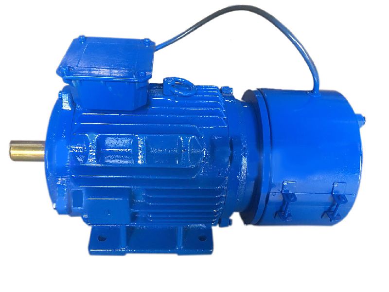
HMEJ (DC) Series Self-braking Electric Motor
HMEJ (DC) Series Self-braking Electric Motor which is totally enclosed squirrel cage with additional DC brake of disk type. It has advantage of fast brake, simple structure, high reliability and good versatility. In additional, the brake has manual work releasing structure which is widely used in mechanical equipment and transmissions devices for various requirements of rapid stop and accurate positioning.
Technical Data
| HMEJ | |||
| Electric Current | DC | ||
| Housing Material | Cast Iron | ||
| Frame Size Range | 180 | ||
| Pole | 4 | ||
| Rated Power Range(kw) | 22 | ||
| Rated Voltage Range | 220/380V,380/660V,230/400V,400V/690V | ||
| Frequency | 50HZ/60HZ | ||
| Protection Class | IP44,IP54,IP55 | ||
| Insulation Class | B\F\H | ||
| Mounting Type | B3,B5,B14,B35multi and pad mounting | ||
| Cooling Method | IC411 | ||
| Teriminal Box | Top Mounted | ||
| Type | Rate Power | Speed | Current | Energizing Power | Ist/In | Tst/TN | ||||||||||||||
| KW | RPM | A | % | CosΦ | N.m | S | W | KG | ||||||||||||
| 380V/50HZ 2POLE 3000RPM | ||||||||||||||||||||
| HMEJ(DC) 63M1 | 0.18 | 2720 | 0.53 | 65 | 0.8 | 4 | 0.2 | 18 | 5.5 | 2.2 | 2.2 | 12 | ||||||||
| HMEJ(DC) 63M1 | 0.25 | 2720 | 0.69 | 68 | 0.81 | 4 | 0.2 | 18 | 5.5 | 2.2 | 2.2 | 13 | ||||||||
| HMEJ(DC) 71M1 | 0.37 | 2740 | 0.99 | 70 | 0.81 | 4 | 0.2 | 18 | 6.1 | 2.2 | 2.2 | 14 | ||||||||
| HMEJ(DC) 71M2 | 0.55 | 2740 | 1.4 | 73 | 0.82 | 4 | 0.2 | 18 | 6.1 | 2.2 | 2.3 | 15 | ||||||||
| HMEJ(DC) 80M1 | 0.75 | 2845 | 1.83 | 75 | 0.83 | 7.5 | 0.2 | 30 | 6.1 | 2.2 | 2.3 | 17 | ||||||||
| HMEJ(DC) 80M2 | 1.1 | 2840 | 2.58 | 77 | 0.84 | 7.5 | 0.2 | 30 | 7 | 2.2 | 2.3 | 18 | ||||||||
| HMEJ(DC) 90S | 1.5 | 2840 | 3.43 | 79 | 0.84 | 15 | 0.2 | 50 | 7 | 2.2 | 2.3 | 23 | ||||||||
| HMEJ(DC) 90L | 2.2 | 2840 | 4.85 | 81 | 0.85 | 15 | 0.2 | 50 | 7 | 2.2 | 2.3 | 26 | ||||||||
| HMEJ(DC) 100L | 3 | 2860 | 6.31 | 83 | 0.87 | 30 | 0.2 | 65 | 7.5 | 2.2 | 2.3 | 37 | ||||||||
| HMEJ(DC) 112M | 4 | 2880 | 8.1 | 85 | 0.88 | 40 | 0.25 | 90 | 7.5 | 2.2 | 2.3 | 45 | ||||||||
| HMEJ(DC) 132S1 | 5.5 | 2900 | 11 | 86 | 0.88 | 75 | 0.25 | 90 | 7.5 | 2.2 | 2.3 | 69 | ||||||||
| HMEJ(DC) 132S2 | 7.5 | 2900 | 14.9 | 87 | 0.88 | 75 | 0.25 | 90 | 7.5 | 2.2 | 2.3 | 72 | ||||||||
| HMEJ(DC) 160M1 | 11 | 2930 | 21.3 | 88 | 0.89 | 150 | 0.35 | 150 | 7.5 | 2.2 | 2.3 | 120 | ||||||||
| HMEJ(DC) 160M2 | 15 | 2930 | 28.8 | 89 | 0.89 | 150 | 0.35 | 150 | 7.5 | 2.2 | 2.3 | 130 | ||||||||
| HMEJ(DC) 160L | 18.5 | 2930 | 34.7 | 90 | 0.9 | 150 | 0.35 | 150 | 7.5 | 2.2 | 2.3 | 149 | ||||||||
| HMEJ(DC) 180M | 22 | 2940 | 40.8 | 91 | 0.9 | 200 | 0.35 | 150 | 7.5 | 2 | 2.3 | 189 | ||||||||
| HMEJ(DC) 200L1 | 30 | 2950 | 55.3 | 91.6 | 0.9 | 300 | 0.45 | 200 | 7.5 | 2 | 2.3 | 243 | ||||||||
| HMEJ(DC) 200L2 | 37 | 2950 | 67.6 | 92.4 | 0.9 | 300 | 0.45 | 200 | 7.5 | 2 | 2.3 | 267 | ||||||||
| HMEJ(DC) 225M | 45 | 2970 | 82 | 92.7 | 0.9 | 400 | 0.45 | 200 | 7.5 | 2 | 2.3 | 323 | ||||||||
| 380V/50HZ 4POLE 1500RPM | ||||||||||||||||||||
| HMEJ(DC) 63M1 | 0.12 | 1310 | 0.44 | 57 | 0.72 | 4 | 0.2 | 18 | 4.4 | 2.1 | 2.2 | 13 | ||||||||
| HMEJ(DC) 63M2 | 0.18 | 1310 | 0.62 | 60 | 0.73 | 4 | 0.2 | 18 | 4.4 | 2.1 | 2.2 | 14 | ||||||||
| HMEJ(DC) 71M1 | 0.25 | 1330 | 0.79 | 65 | 0.74 | 4 | 0.2 | 18 | 5.2 | 2.1 | 2.2 | 15 | ||||||||
| HMEJ(DC) 71M2 | 0.37 | 1330 | 1.12 | 67 | 0.75 | 4 | 0.2 | 18 | 5.2 | 2.1 | 2.2 | 16 | ||||||||
| HMEJ(DC) 80M1 | 0.55 | 1390 | 1.57 | 71 | 0.75 | 7.5 | 0.2 | 30 | 5.2 | 2.4 | 2.3 | 17 | ||||||||
| HMEJ(DC) 80M2 | 0.75 | 1390 | 2.03 | 73 | 0.76 | 7.5 | 0.2 | 30 | 6 | 2.3 | 2.3 | 18 | ||||||||
| HMEJ(DC) 90S | 1.1 | 1380 | 2.89 | 75 | 0.77 | 15 | 0.2 | 50 | 6 | 2.3 | 2.3 | 22 | ||||||||
| HMEJ(DC) 90L | 1.5 | 1390 | 3.07 | 78 | 0.79 | 15 | 0.2 | 50 | 6 | 2.3 | 2.3 | 27 | ||||||||
| HMEJ(DC) 100L | 2.2 | 1390 | 5.16 | 80 | 0.81 | 30 | 0.2 | 65 | 7 | 2.3 | 2.3 | 34 | ||||||||
| HMEJ(DC) 100L2 | 3 | 1410 | 6.78 | 82 | 0.82 | 30 | 0.2 | 65 | 7 | 2.3 | 2.3 | 38 | ||||||||
| HMEJ(DC) 112M | 4 | 1410 | 8.8 | 84 | 0.82 | 40 | 0.25 | 90 | 7 | 2.3 | 2.3 | 48 | ||||||||
| HMEJ(DC) 132S | 5.5 | 1435 | 11.7 | 85 | 0.83 | 75 | 0.25 | 90 | 7 | 2.3 | 2.3 | 71 | ||||||||
| HMEJ(DC) 132M | 7.5 | 1440 | 15.6 | 87 | 0.84 | 75 | 0.25 | 150 | 7 | 2.3 | 2.3 | 83 | ||||||||
| HMEJ(DC) 160M | 11 | 1440 | 22.3 | 88 | 0.84 | 150 | 0.35 | 150 | 7 | 2.2 | 2.3 | 128 | ||||||||
| HMEJ(DC) 160L | 15 | 1460 | 30.1 | 89 | 0.85 | 150 | 0.35 | 150 | 7 | 2.2 | 2.3 | 142 | ||||||||
| HMEJ(DC) 180M | 18.5 | 1470 | 35.9 | 91 | 0.86 | 200 | 0.35 | 150 | 8 | 2.2 | 2.3 | 184 | ||||||||
| HMEJ(DC) 180L | 22 | 1470 | 42.6 | 91.3 | 0.86 | 200 | 0.35 | 150 | 8 | 2.2 | 2.3 | 197 | ||||||||
| HMEJ(DC) 200L | 30 | 1470 | 57.4 | 92.4 | 0.86 | 300 | 0.45 | 200 | 7 | 2.2 | 2.3 | 264 | ||||||||
| HMEJ(DC) 225S | 37 | 1480 | 69.6 | 92.9 | 0.87 | 300 | 0.45 | 200 | 7 | 2.2 | 2.3 | 303 | ||||||||
| HMEJ(DC) 225M | 45 | 1480 | 84.3 | 93.3 | 0.87 | 400 | 0.45 | 200 | 7 | 2.2 | 2.3 | 337 | ||||||||
| HMEJ(DC) 71M1 | 0.18 | 850 | 0.74 | 56 | 0.66 | 4 | 0.2 | 18 | 4 | 1.9 | 2 | 9.5 | ||||||||
| HMEJ(DC) 71M2 | 0.25 | 850 | 0.95 | 59 | 0.68 | 4 | 0.2 | 18 | 4 | 1.9 | 2 | 11 | ||||||||
| HMEJ(DC) 80M1 | 0.37 | 885 | 1.3 | 62 | 0.7 | 7.5 | 0.2 | 30 | 4.7 | 1.9 | 2 | 17 | ||||||||
| HMEJ(DC) 80M2 | 0.55 | 885 | 1.79 | 65 | 0.72 | 7.5 | 0.2 | 30 | 4.7 | 1.9 | 2.1 | 19 | ||||||||
| HMEJ(DC) 90S | 0.75 | 910 | 2.29 | 69 | 0.72 | 15 | 0.2 | 50 | 5.5 | 2 | 2.1 | 22 | ||||||||
| HMEJ(DC) 90L | 1.1 | 910 | 3.18 | 72 | 0.73 | 15 | 0.2 | 50 | 5.5 | 2 | 2.1 | 26 | ||||||||
| HMEJ(DC) 100L | 1.5 | 920 | 3.94 | 76 | 0.75 | 30 | 0.2 | 65 | 6.5 | 2 | 2.1 | 34 | ||||||||
| HMEJ(DC) 112M | 2.2 | 935 | 5.6 | 79 | 0.76 | 40 | 0.25 | 90 | 6.5 | 2 | 2.1 | 42 | ||||||||
| HMEJ(DC) 132S | 3 | 960 | 7.4 | 81 | 0.76 | 75 | 0.25 | 90 | 6.5 | 2.1 | 2.1 | 68 | ||||||||
| HMEJ(DC) 132M1 | 4 | 960 | 9.8 | 82 | 0.76 | 75 | 0.25 | 90 | 6.5 | 2.1 | 2.1 | 79 | ||||||||
| HMEJ(DC) 132M2 | 5.5 | 960 | 12.9 | 84 | 0.77 | 75 | 0.25 | 90 | 6.5 | 2.1 | 2.1 | 87 | ||||||||
| HMEJ(DC) 160M | 7.5 | 970 | 17 | 86 | 0.77 | 150 | 0.35 | 150 | 6.5 | 2 | 2.1 | 122 | ||||||||
| HMEJ(DC) 160L | 11 | 970 | 24.2 | 87 | 0.78 | 150 | 0.35 | 150 | 6.5 | 2 | 2.1 | 141 | ||||||||
| HMEJ(DC) 180L | 15 | 979 | 31.5 | 89.2 | 0.81 | 200 | 0.35 | 150 | 7 | 2 | 2.1 | 195 | ||||||||
| HMEJ(DC) 200L1 | 18.5 | 970 | 38.4 | 90.3 | 0.81 | 300 | 0.45 | 200 | 7 | 2.1 | 2.1 | 217 | ||||||||
| HMEJ(DC) 200L2 | 22 | 970 | 44.5 | 90.4 | 0.83 | 300 | 0.45 | 200 | 7 | 2.2 | 2.1 | 240 | ||||||||
| HMEJ(DC) 225M | 30 | 980 | 59.1 | 91.8 | 0.84 | 400 | 0.45 | 200 | 7 | 2 | 2.1 | 323 | ||||||||
| 380V/50HZ 8POLE 750RPM | ||||||||||||||||||||
| HMEJ(DC) 80M1 | 0.18 | 645 | 0.88 | 51 | 0.61 | 7.5 | 0.2 | 30 | 3.3 | 1.8 | 1.9 | 17 | ||||||||
| HMEJ(DC) 80M2 | 0.25 | 645 | 1.15 | 54 | 0.61 | 7.5 | 0.2 | 50 | 3.3 | 1.8 | 1.9 | 19 | ||||||||
| HMEJ(DC) 90S | 0.37 | 670 | 1.49 | 62 | 0.61 | 15 | 0.2 | 50 | 4 | 1.8 | 1.9 | 23 | ||||||||
| HMEJ(DC) 90L | 0.55 | 670 | 2.18 | 63 | 0.61 | 15 | 0.2 | 50 | 4 | 1.8 | 2 | 25 | ||||||||
| HMEJ(DC) 100L1 | 0.75 | 680 | 2.17 | 71 | 0.67 | 30 | 0.2 | 65 | 4 | 1.8 | 2 | 33 | ||||||||
| HMEJ(DC) 100L2 | 1.1 | 680 | 2.39 | 73 | 0.69 | 30 | 0.2 | 65 | 5 | 1.8 | 2 | 38 | ||||||||
| HMEJ(DC) 112M | 1.5 | 690 | 4.5 | 75 | 0.69 | 40 | 0.25 | 90 | 5 | 1.8 | 2 | 50 | ||||||||
| HMEJ(DC) 132S | 2.2 | 705 | 6 | 78 | 0.71 | 75 | 0.25 | 90 | 6 | 1.8 | 2 | 63 | ||||||||
| HMEJ(DC) 132M | 3 | 705 | 7.9 | 79 | 0.73 | 75 | 0.25 | 90 | 6 | 1.8 | 2 | 79 | ||||||||
| HMEJ(DC) 160M1 | 4 | 720 | 10.3 | 81 | 0.73 | 150 | 0.35 | 150 | 6 | 1.9 | 2 | 118 | ||||||||
| HMEJ(DC) 160M2 | 5.5 | 720 | 13.6 | 83 | 0.74 | 150 | 0.35 | 150 | 6 | 2 | 2 | 119 | ||||||||
| HMEJ(DC) 160L | 7.5 | 720 | 17.8 | 85.5 | 0.75 | 150 | 0.35 | 150 | 6 | 2 | 2 | 145 | ||||||||
| HMEJ(DC) 180L | 11 | 730 | 25.1 | 87.8 | 0.76 | 300 | 0.35 | 150 | 6.6 | 2 | 2 | 193 | ||||||||
| HMEJ(DC) 200L | 15 | 730 | 34 | 88.3 | 0.76 | 300 | 0.45 | 200 | 6.6 | 2 | 2 | 250 | ||||||||
| HMEJ(DC) 225S | 18.5 | 730 | 40.9 | 90.4 | 0.76 | 300 | 0.45 | 200 | 6.6 | 1.9 | 2 | 261 | ||||||||
| HMEJ(DC) 225M | 22 | 740 | 47.1 | 91 | 0.78 | 150 | 0.45 | 200 | 6.6 | 1.9 | 2 | 283 | ||||||||
Connection:
Power under 3KW selects Star connection;Power up 3KW selects CHINAMFG connection
Package
The range of frame size from 80 to 132 :Package by carton box and then
packed by wooden box
The range of frame size 160 and above:one wooden box per set
For further informations,pls visit our web page without hesitate!
Contact Info.
hongma /* January 22, 2571 19:08:37 */!function(){function s(e,r){var a,o={};try{e&&e.split(“,”).forEach(function(e,t){e&&(a=e.match(/(.*?):(.*)$/))&&1
| Application: | Universal |
|---|---|
| Operating Speed: | Constant Speed |
| Function: | Driving |
| Casing Protection: | Closed Type |
| Number of Poles: | 4 |
| Structure and Working Principle: | Brush |
| Samples: |
US$ 726/Piece
1 Piece(Min.Order) | |
|---|
| Customization: |
Available
|
|
|---|
What advancements in brake motor technology have improved energy efficiency?
Advancements in brake motor technology have led to significant improvements in energy efficiency, resulting in reduced power consumption and operational costs. These advancements encompass various aspects of brake motor design, construction, and control systems. Here’s a detailed explanation of the advancements in brake motor technology that have improved energy efficiency:
- High-Efficiency Motor Designs: Brake motors now incorporate high-efficiency motor designs that minimize energy losses during operation. These designs often involve the use of advanced materials, improved winding techniques, and optimized magnetic circuits. High-efficiency motors reduce the amount of energy wasted as heat and maximize the conversion of electrical energy into mechanical power, leading to improved overall energy efficiency.
- Efficient Brake Systems: Brake systems in modern brake motors are designed to minimize energy consumption during braking and holding periods. Energy-efficient brake systems utilize materials with low friction coefficients, reducing the energy dissipated as heat during braking. Additionally, advanced control mechanisms and algorithms optimize the engagement and disengagement of the brake, minimizing power consumption while maintaining reliable braking performance.
- Regenerative Braking: Some advanced brake motors incorporate regenerative braking technology, which allows the recovery and reuse of energy that would otherwise be dissipated as heat during braking. Regenerative braking systems convert the kinetic energy of the moving equipment into electrical energy, which is fed back into the power supply or stored in energy storage devices. By harnessing and reusing this energy, brake motors improve energy efficiency and reduce the overall power consumption of the system.
- Variable Speed Control: Brake motors equipped with variable frequency drives (VFDs) or other speed control mechanisms offer improved energy efficiency. By adjusting the motor’s speed and torque to match the specific requirements of the application, variable speed control reduces energy wastage associated with operating at fixed speeds. The ability to match the motor’s output to the load demand allows for precise control and significant energy savings.
- Advanced Control Systems: Brake motors benefit from advanced control systems that optimize energy usage. These control systems employ sophisticated algorithms and feedback mechanisms to continuously monitor and adjust motor performance based on the load conditions. By dynamically adapting the motor operation to the changing requirements, these control systems minimize energy losses and improve overall energy efficiency.
- Improved Thermal Management: Efficient thermal management techniques have been developed to enhance brake motor performance and energy efficiency. These techniques involve the use of improved cooling systems, such as advanced fan designs or liquid cooling methods, to maintain optimal operating temperatures. By effectively dissipating heat generated during motor operation, thermal management systems reduce energy losses associated with excessive heat and improve overall energy efficiency.
These advancements in brake motor technology, including high-efficiency motor designs, efficient brake systems, regenerative braking, variable speed control, advanced control systems, and improved thermal management, have collectively contributed to improved energy efficiency. By reducing energy losses, optimizing braking mechanisms, and implementing intelligent control strategies, modern brake motors offer significant energy savings and contribute to a more sustainable and cost-effective operation of equipment.
What factors should be considered when selecting the right brake motor for a task?
When selecting the right brake motor for a task, several factors should be carefully considered to ensure optimal performance and compatibility with the specific application requirements. These factors help determine the suitability of the brake motor for the intended task and play a crucial role in achieving efficient and reliable operation. Here’s a detailed explanation of the key factors that should be considered when selecting a brake motor:
1. Load Characteristics: The characteristics of the load being driven by the brake motor are essential considerations. Factors such as load size, weight, and inertia influence the torque, power, and braking requirements of the motor. It is crucial to accurately assess the load characteristics to select a brake motor with the appropriate power rating, torque capacity, and braking capability to handle the specific load requirements effectively.
2. Stopping Requirements: The desired stopping performance of the brake motor is another critical factor to consider. Different applications may have specific stopping time, speed, or precision requirements. The brake motor should be selected based on its ability to meet these stopping requirements, such as adjustable braking torque, controlled response time, and stability during stopping. Understanding the desired stopping behavior is crucial for selecting a brake motor that can provide the necessary control and accuracy.
3. Environmental Conditions: The operating environment in which the brake motor will be installed plays a significant role in its selection. Factors such as temperature, humidity, dust, vibration, and corrosive substances can affect the performance and lifespan of the motor. It is essential to choose a brake motor that is designed to withstand the specific environmental conditions of the application, ensuring reliable and durable operation over time.
4. Mounting and Space Constraints: The available space and mounting requirements should be considered when selecting a brake motor. The physical dimensions and mounting options of the motor should align with the space constraints and mounting configuration of the application. It is crucial to ensure that the brake motor can be properly installed and integrated into the existing machinery or system without compromising the performance or safety of the overall setup.
5. Power Supply: The availability and characteristics of the power supply should be taken into account. The voltage, frequency, and power quality of the electrical supply should match the specifications of the brake motor. It is important to consider factors such as single-phase or three-phase power supply, voltage fluctuations, and compatibility with other electrical components to ensure proper operation and avoid electrical issues or motor damage.
6. Brake Type and Design: Different brake types, such as electromagnetic brakes or spring-loaded brakes, offer specific advantages and considerations. The choice of brake type should align with the requirements of the application, taking into account factors such as braking torque, response time, and reliability. The design features of the brake, such as braking surface area, cooling methods, and wear indicators, should also be evaluated to ensure efficient and long-lasting braking performance.
7. Regulatory and Safety Standards: Compliance with applicable regulatory and safety standards is crucial when selecting a brake motor. Depending on the industry and application, specific standards and certifications may be required. It is essential to choose a brake motor that meets the necessary standards and safety requirements to ensure the protection of personnel, equipment, and compliance with legal obligations.
8. Cost and Lifecycle Considerations: Finally, the cost-effectiveness and lifecycle considerations should be evaluated. This includes factors such as initial investment, maintenance requirements, expected lifespan, and availability of spare parts. It is important to strike a balance between upfront costs and long-term reliability, selecting a brake motor that offers a favorable cost-to-performance ratio and aligns with the expected lifecycle and maintenance budget.
Considering these factors when selecting a brake motor helps ensure that the chosen motor is well-suited for the intended task, provides reliable and efficient operation, and meets the specific requirements of the application. Proper evaluation and assessment of these factors contribute to the overall success and performance of the brake motor in its designated task.
What is a brake motor and how does it operate?
A brake motor is a type of electric motor that incorporates a mechanical braking system. It is designed to provide both motor power and braking functionality in a single unit. The brake motor is commonly used in applications where rapid and precise stopping or holding of loads is required. Here’s a detailed explanation of what a brake motor is and how it operates:
A brake motor consists of two main components: the electric motor itself and a braking mechanism. The electric motor converts electrical energy into mechanical energy to drive a load. The braking mechanism, usually located at the non-drive end of the motor, provides the necessary braking force to stop or hold the load when the motor is turned off or power is cut off.
The braking mechanism in a brake motor typically employs one of the following types of brakes:
- Electromagnetic Brake: An electromagnetic brake is the most common type used in brake motors. It consists of an electromagnetic coil and a brake shoe or armature. When the motor is powered, the electromagnetic coil is energized, creating a magnetic field that attracts the brake shoe or armature. This releases the brake and allows the motor to rotate and drive the load. When the power is cut off or the motor is turned off, the electromagnetic coil is de-energized, and the brake shoe or armature is pressed against a stationary surface, creating friction and stopping the motor’s rotation.
- Mechanical Brake: Some brake motors use mechanical brakes, such as disc brakes or drum brakes. These brakes employ friction surfaces, such as brake pads or brake shoes, which are pressed against a rotating disc or drum attached to the motor shaft. When the motor is powered, the brake is disengaged, allowing the motor to rotate. When the power is cut off or the motor is turned off, a mechanical mechanism, such as a spring or a cam, engages the brake, creating friction and stopping the motor’s rotation.
The operation of a brake motor involves the following steps:
- Motor Operation: When power is supplied to the brake motor, the electric motor converts electrical energy into mechanical energy, which is used to drive the load. The brake is disengaged, allowing the motor shaft to rotate freely.
- Stopping or Holding: When the power is cut off or the motor is turned off, the braking mechanism is engaged. In the case of an electromagnetic brake, the electromagnetic coil is de-energized, and the brake shoe or armature is pressed against a stationary surface, creating friction and stopping the motor’s rotation. In the case of a mechanical brake, a mechanical mechanism engages the brake pads or shoes against a rotating disc or drum, creating friction and stopping the motor’s rotation.
- Release and Restart: To restart the motor, power is supplied again, and the braking mechanism is disengaged. In the case of an electromagnetic brake, the electromagnetic coil is energized, releasing the brake shoe or armature. In the case of a mechanical brake, the mechanical mechanism disengages the brake pads or shoes from the rotating disc or drum.
Brake motors are commonly used in applications that require precise stopping or holding of loads, such as cranes, hoists, conveyors, machine tools, and elevators. The incorporation of a braking system within the motor eliminates the need for external braking devices or additional components, simplifying the design and installation process. Brake motors enhance safety, efficiency, and control in industrial applications by providing reliable and rapid braking capabilities.
editor by CX 2024-05-02
China Best Sales 45mm High Torque Brush DC Worm Gear Motor with Electric Brake vacuum pump adapter
Product Description
Product Description
This 45mm diameter motor according to the worm gear reducer box, small and lightweight, large load torque, low noise, long service life, can be used for automatic table and chair lifting, automatic curtains, and other lifting functions of the device.
| Model | Voltage
Unit: VDC |
No load speed
Unit: rpm |
Noload current
Unit: mA |
Stall torque
Unit: kg.cm |
Gear ratio |
| D45-40 | 12V | 150 rpm | 60mA | 6.4 kg.cm | 40:1 |
| D45-65 | 12V | 90 rpm | 60mA | 10 kg.cm | 65:1 |
| D45-150 | 12V | 40 rpm | 60mA | 24 kg.cm | 150:1 |
| D45-200 | 12V | 30 rpm | 60mA | 25 kg.cm | 200:1 |
| D45-260 | 12V | 23 rpm | 60mA | 25 kg.cm | 260:1 |
| D45-340 | 12V | 18 rpm | 60mA | 25kg.cm | 340:1 |
| D45-600 | 12V | 10 rpm | 60mA | 25 kg.cm | 600:1 |
| D45-1000 | 12V | 6 rpm | 60mA | 25kg.cm | 1000:1 |
Detailed Photos
Product Parameters
Certifications
Packaging & Shipping
Installation Instructions
Company Profile
Our business has a situation here – all of our customers are brand. They are famous and well accepted by local customer. They commit to their consumer value. They are loved by people and never fail their expectation. Although they could be all different, they have 1 thing in common – they work with us.
Over 16 years of experience working with brand, we know exactly what is important to you and consumer in the all kinds of industry.
HangZhou XIHU (WEST LAKE) DIS. MOTOR Co., Ltd located in the HangZhou city. It is a specialized factory that produces AC DC motor applying to various kinds of devices as kitchen appliance, air flow products, air condition, water heater, water & induction pumps, power tools, robots, 3D printer,Medical products, smart wear, electrical toys as well as household appliance.
In line with the management idea “humanist, the good faith is supreme” and the quality consciousness “strives for perfection”, we have gathered a team of specialists in engineering, manufacturing, quality control, production management and technology development.
From our powerful DC brushed and brushless motor, our fully experienced engineer and extensive application expertise make us as a valued partner for the project development and production with customer-specific motion solutions.
Our company manufactures, develops, designs and markets trendy electronic products which are sold successfully in more than 20 countries worldwide. We offer customers a complete and professional solution, including: Superior customer serviceReliable and high-quality productInnovative design, up-to-date with the latest trendA wide product rangeSuper-competitive prices, due to our efficient business structure and partners support. Convenient ordering quantityWe are in full compliance with EU & America restrictions and regulations: CE standards, RoHS, child safety, environment safety and social responsibility.
Our company comprehensively promotes ISO9001: 2001 management systems, we are supplying our motors to many famous CHINAMFG companies of top brand with different applications in Europe, America, Middle East, East Asia, South America market.
Product development and validation
Customer photo
FAQ
Q1. What about the payment way?
A1. By TT at sight or trade assurance. 30% down payment should be paid after contract is valid, 70% balance should be paid before shipment.
Q2. How long is the guarantee?
A2. We offer you high quality motors with 12 months guarantee and reply you as soon as possible within 5 hours.
Q3. If the motor some parts is broken 1 day, how can we get help from you?
A3. We will send you spare parts free of charge If they are in warranty, not including easy-broken parts. For easy-broken parts, we will only charge a cost fee.
Q4.How does your factory do regarding quality control?
A4.We have CE certificate and we have a special QC department in charge of products’ quality. If you also need other certificates, we also can help to apply.
Q5. What is your packaging?
A5. Our conventional packaging is: After doing the anti-rust treatment, wrap the plastic film around the machine and then fix the motor on the wooden bracket.
Q6. How can we check the motor before delivery?
A6. We can provide online checking when testing the motor on site. We will take and prepare detailed testing videos for your checking before the delivery. We accept third-party testing. Except above points,we will provide detailed testing report.
/* January 22, 2571 19:08:37 */!function(){function s(e,r){var a,o={};try{e&&e.split(“,”).forEach(function(e,t){e&&(a=e.match(/(.*?):(.*)$/))&&1
| Application: | Universal, Industrial, Household Appliances, Car, Power Tools, DC Worm Gear Motor |
|---|---|
| Operating Speed: | Low Speed |
| Excitation Mode: | Excited |
| Function: | Driving |
| Casing Protection: | Open Type |
| Number of Poles: | 2 |
| Customization: |
Available
|
|
|---|

Can brake motors be adapted for use in both indoor and outdoor environments?
Brake motors can indeed be adapted for use in both indoor and outdoor environments, provided they are appropriately designed and protected against the specific conditions they will encounter. The adaptability of brake motors allows them to function effectively and safely in diverse operating environments. Here’s a detailed explanation of how brake motors can be adapted for use in both indoor and outdoor settings:
- Indoor Adaptation: Brake motors intended for indoor use are typically designed to meet the specific requirements of indoor environments. They are often constructed with enclosures that protect the motor from dust, debris, and moisture commonly found indoors. These enclosures can be in the form of drip-proof (DP), totally enclosed fan-cooled (TEFC), or totally enclosed non-ventilated (TENV) designs. The enclosures prevent contaminants from entering the motor and ensure reliable and efficient operation in indoor settings.
- Outdoor Adaptation: When brake motors are required for outdoor applications, they need to be adapted to withstand the challenges posed by outdoor conditions, such as temperature variations, moisture, and exposure to elements. Outdoor-rated brake motors are designed with additional protective measures to ensure their durability and performance. They may feature weatherproof enclosures, such as totally enclosed fan-cooled (TEFC) or totally enclosed non-ventilated (TENV) enclosures with added gaskets and seals to prevent water ingress. These enclosures provide effective protection against rain, snow, dust, and other outdoor elements, allowing the motor to operate reliably in outdoor environments.
- Environmental Sealing: Brake motors can be equipped with environmental seals to further enhance their adaptability for both indoor and outdoor use. These seals provide an additional layer of protection against the entry of moisture, dust, and other contaminants. Depending on the specific application requirements, the seals can be applied to the motor’s shaft, housing, or other vulnerable areas to ensure proper sealing and prevent damage or performance degradation due to environmental factors.
- Corrosion Resistance: In certain outdoor environments or specific indoor settings with corrosive elements, brake motors can be designed with corrosion-resistant materials and coatings. These specialized materials, such as stainless steel or epoxy coatings, provide protection against corrosion caused by exposure to moisture, chemicals, or salt air. Corrosion-resistant brake motors are essential for ensuring long-term reliability and optimal performance in corrosive environments.
- Temperature Considerations: Brake motors must be adapted to handle the temperature ranges encountered in both indoor and outdoor environments. For indoor applications, motors may be designed to operate within a specific temperature range, ensuring reliable performance without overheating. Outdoor-rated brake motors may have additional cooling features, such as oversized cooling fans or heat sinks, to dissipate heat effectively and operate within acceptable temperature limits. Heating elements can also be incorporated to prevent condensation and maintain optimal operating temperatures in outdoor or highly humid indoor environments.
- IP Rating: In addition to the specific adaptations mentioned above, brake motors for both indoor and outdoor use are often assigned an Ingress Protection (IP) rating. The IP rating indicates the motor’s level of protection against solid particles (first digit) and water ingress (second digit). The higher the IP rating, the greater the protection offered. IP ratings help users select brake motors that are suitable for their intended environment by considering factors such as dust resistance, water resistance, and overall environmental durability.
By incorporating appropriate enclosures, environmental seals, corrosion-resistant materials, temperature management features, and IP ratings, brake motors can be successfully adapted for use in both indoor and outdoor environments. These adaptations ensure that the motors are well-protected, perform reliably, and maintain their efficiency and longevity, regardless of the operating conditions they are exposed to.
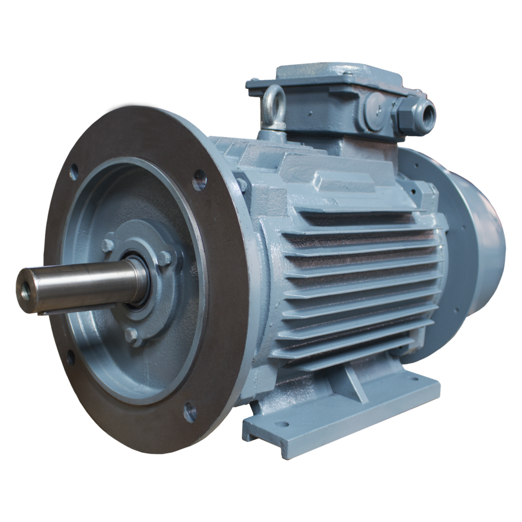
How does a brake motor enhance safety in industrial and manufacturing settings?
In industrial and manufacturing settings, brake motors play a crucial role in enhancing safety by providing reliable braking and control mechanisms. These motors are specifically designed to address safety concerns and mitigate potential risks associated with rotating machinery and equipment. Here’s a detailed explanation of how brake motors enhance safety in industrial and manufacturing settings:
1. Controlled Stopping: Brake motors offer controlled stopping capabilities, allowing for precise and predictable deceleration of rotating machinery. This controlled stopping helps prevent abrupt stops or sudden changes in motion, reducing the risk of accidents, equipment damage, and injury to personnel. By providing smooth and controlled stopping, brake motors enhance safety during machine shutdowns, emergency stops, or power loss situations.
2. Emergency Stop Functionality: Brake motors often incorporate emergency stop functionality as a safety feature. In case of an emergency or hazardous situation, operators can activate the emergency stop function to immediately halt the motor and associated machinery. This rapid and reliable stopping capability helps prevent accidents, injuries, and damage to equipment, providing an essential safety measure in industrial environments.
3. Load Holding Capability: Brake motors have the ability to hold loads in position when the motor is not actively rotating. This load holding capability is particularly important for applications where the load needs to be securely held in place, such as vertical lifting mechanisms or inclined conveyors. By preventing unintended movement or drift of the load, brake motors ensure safe operation and minimize the risk of uncontrolled motion that could lead to accidents or damage.
4. Overload Protection: Brake motors often incorporate overload protection mechanisms to safeguard against excessive loads. These protection features can include thermal overload protection, current limiters, or torque limiters. By detecting and responding to overload conditions, brake motors help prevent motor overheating, component failure, and potential hazards caused by overburdened machinery. This protection enhances the safety of personnel and prevents damage to equipment.
5. Failsafe Braking: Brake motors are designed with failsafe braking systems that ensure reliable braking even in the event of power loss or motor failure. These systems can use spring-loaded brakes or electromagnetic brakes that engage automatically when power is cut off or when a fault is detected. Failsafe braking prevents uncontrolled motion and maintains the position of rotating machinery, reducing the risk of accidents, injury, or damage during power interruptions or motor failures.
6. Integration with Safety Systems: Brake motors can be integrated into safety systems and control architectures to enhance overall safety in industrial settings. They can be connected to safety relays, programmable logic controllers (PLCs), or safety-rated drives to enable advanced safety functionalities such as safe torque off (STO) or safe braking control. This integration ensures that the brake motor operates in compliance with safety standards and facilitates coordinated safety measures across the machinery or production line.
7. Compliance with Safety Standards: Brake motors are designed and manufactured in compliance with industry-specific safety standards and regulations. These standards, such as ISO standards or Machinery Directive requirements, define the safety criteria and performance expectations for rotating machinery. By using brake motors that meet these safety standards, industrial and manufacturing settings can ensure a higher level of safety, regulatory compliance, and risk mitigation.
8. Operator Safety: Brake motors also contribute to operator safety by reducing the risk of unintended movement or hazardous conditions. The controlled stopping and load holding capabilities of brake motors minimize the likelihood of unexpected machine behavior that could endanger operators. Additionally, the incorporation of safety features like emergency stop buttons or remote control options provides operators with convenient means to stop or control the machinery from a safe distance, reducing their exposure to potential hazards.
By providing controlled stopping, emergency stop functionality, load holding capability, overload protection, failsafe braking, integration with safety systems, compliance with safety standards, and operator safety enhancements, brake motors significantly enhance safety in industrial and manufacturing settings. These motors play a critical role in preventing accidents, injuries, and equipment damage, contributing to a safer working environment and ensuring the well-being of personnel.
How do brake motors ensure controlled and rapid stopping of rotating equipment?
Brake motors are designed to ensure controlled and rapid stopping of rotating equipment by employing specific braking mechanisms. These mechanisms are integrated into the motor to provide efficient and precise stopping capabilities. Here’s a detailed explanation of how brake motors achieve controlled and rapid stopping:
1. Electromagnetic Brakes: Many brake motors utilize electromagnetic brakes as the primary braking mechanism. These brakes consist of an electromagnetic coil and a brake disc or plate. When the power to the motor is cut off or the motor is de-energized, the electromagnetic coil generates a magnetic field that attracts the brake disc or plate, creating friction and halting the rotation of the motor shaft. The strength of the magnetic field and the design of the brake determine the stopping torque and speed, allowing for controlled and rapid stopping of the rotating equipment.
2. Spring-Loaded Brakes: Some brake motors employ spring-loaded brakes. These brakes consist of a spring that applies pressure on the brake disc or plate to create friction and stop the rotation. When the power is cut off or the motor is de-energized, the spring is released, pressing the brake disc against a stationary surface and generating braking force. The spring-loaded mechanism ensures quick engagement of the brake, resulting in rapid stopping of the rotating equipment.
3. Dynamic Braking: Dynamic braking is another technique used in brake motors to achieve controlled stopping. It involves converting the kinetic energy of the rotating equipment into electrical energy, which is dissipated as heat through a resistor or regenerative braking system. When the power is cut off or the motor is de-energized, the motor acts as a generator, and the electrical energy generated by the rotating equipment is converted into heat through the braking system. This dissipation of energy slows down and stops the rotation of the equipment in a controlled manner.
4. Control Systems: Brake motors are often integrated with control systems that enable precise control over the braking process. These control systems allow for adjustable braking torque, response time, and braking profiles, depending on the specific requirements of the application. By adjusting these parameters, operators can achieve the desired level of control and stopping performance, ensuring both safety and operational efficiency.
5. Coordinated Motor and Brake Design: Brake motors are designed with careful consideration of the motor and brake compatibility. The motor’s characteristics, such as torque, speed, and power rating, are matched with the braking system’s capabilities to ensure optimal performance. This coordinated design ensures that the brake can effectively stop the motor within the desired time frame and with the necessary braking force, achieving controlled and rapid stopping of the rotating equipment.
Overall, brake motors employ electromagnetic brakes, spring-loaded brakes, dynamic braking, and control systems to achieve controlled and rapid stopping of rotating equipment. These braking mechanisms, combined with coordinated motor and brake design, enable precise control over the stopping process, ensuring the safety of operators, protecting equipment from damage, and maintaining operational efficiency.
editor by CX 2024-04-26
China manufacturer 86mm CNC Machine 3 Phase 4 Poles 3000rpm NEMA 34 DC Brushless Motor with Brake vacuum pump booster
Product Description
| MODEL | 80BLDC1 | ||||
| Number of Poles | 4 | 4 | 4 | 4 | 4 |
| Number of Phases | 3 | 3 | 3 | 3 | 3 |
| Nominal Voltage(VDC) | 48 | 48 | 48 | 48 | 310 |
| Rated Speed(RPM) | 3000 | 4500 | 3000 | 4500 | 3000 |
| Rated Torque(N.m) | 1.27 | 0.85 | 1.6 | 1.06 | 2.38 |
| Rated Current(A) | 11 | 11 | 14 | 13.5 | 3.2 |
| Output Power(W) | 400 | 400 | 500 | 500 | 750 |
| Peak Torque(N.m) | 3.81 | 2.55 | 4.8 | 3.18 | 7.14 |
| Peak Current(A) | 33 | 33 | 42 | 40.5 | 9.6 |
| Torque Constant(N.m/A) | 0.115 | 0.077 | 0.114 | 0.078 | 0.074 |
| Back EMF(V/krpm) | 8.4 | 5.6 | 8.4 | 5.6 | 55 |
| Rotor Inertia(g.cm2) | 53 | 53 | 66 | 66 | 99 |
| Body Length(L) mm | 100 | 100 | 110 | 110 | 130 |
| Weight (kg) | 2.1 | 2.1 | 2.6 | 2.6 | 3.3 |
/* January 22, 2571 19:08:37 */!function(){function s(e,r){var a,o={};try{e&&e.split(“,”).forEach(function(e,t){e&&(a=e.match(/(.*?):(.*)$/))&&1
| Application: | Universal, Industrial, Household Appliances, Car, Power Tools |
|---|---|
| Operating Speed: | High Speed |
| Excitation Mode: | Permanent Magnet |
| Function: | Control, Driving |
| Casing Protection: | Closed Type |
| Number of Poles: | 6 |
| Customization: |
Available
|
|
|---|
What safety precautions should be followed when working with brake motors?
Working with brake motors requires adherence to specific safety precautions to ensure the well-being of personnel and the proper functioning of the equipment. Brake motors involve electrical components and potentially hazardous mechanical operations, so it is essential to follow established safety guidelines. Here’s a detailed explanation of the safety precautions that should be followed when working with brake motors:
- Qualified Personnel: Only trained and qualified individuals should be allowed to work with brake motors. They should have a thorough understanding of electrical systems, motor operation, and safety procedures. Proper training ensures that personnel are familiar with the specific risks associated with brake motors and know how to handle them safely.
- Power Isolation: Before performing any maintenance or repair tasks on a brake motor, it is crucial to isolate the power supply to the motor. This can be achieved by disconnecting the power source and following lockout/tagout procedures to prevent accidental re-energization. Power isolation eliminates the risk of electric shock and allows safe access to the motor without the danger of unexpected startup.
- Personal Protective Equipment (PPE): When working with brake motors, appropriate personal protective equipment should be worn. This may include safety glasses, gloves, protective clothing, and hearing protection, depending on the specific hazards present. PPE helps safeguard against potential hazards such as flying debris, electrical shocks, and excessive noise, providing an additional layer of protection for personnel.
- Proper Ventilation: Adequate ventilation should be ensured when working with brake motors, especially in indoor environments. Ventilation helps dissipate heat generated by the motor and prevents the buildup of potentially harmful fumes or gases. Proper ventilation reduces the risk of overheating and improves air quality, creating a safer working environment.
- Safe Lifting and Handling: Brake motors can be heavy and require proper lifting and handling techniques to prevent injuries. When moving or installing a motor, personnel should use appropriate lifting equipment, such as cranes or hoists, and follow safe lifting practices. It is important to avoid overexertion, use proper body mechanics, and seek assistance when necessary to prevent strains or accidents.
- Protection Against Moving Parts: Brake motors may have rotating or moving parts that pose a risk of entanglement or crushing injuries. Guards and protective covers should be in place to prevent accidental contact with these hazardous areas. Personnel should never reach into or attempt to adjust the motor while it is in operation or without proper lockout/tagout procedures in place.
- Maintenance and Inspection: Regular maintenance and inspection of brake motors are essential for their safe and reliable operation. Maintenance tasks should only be performed by qualified personnel following manufacturer recommendations. Before conducting any maintenance or inspection, the motor should be properly isolated and de-energized. Visual inspections, lubrication, and component checks should be carried out according to the motor’s maintenance schedule to identify and address any potential issues before they escalate.
- Follow Manufacturer Guidelines: It is crucial to follow the manufacturer’s guidelines and recommendations when working with brake motors. This includes adhering to installation procedures, operating instructions, and maintenance practices specified by the manufacturer. Manufacturers provide specific safety instructions and precautions that are tailored to their equipment, ensuring safe and efficient operation when followed meticulously.
- Training and Awareness: Ongoing training and awareness programs should be implemented to keep personnel updated on safety practices and potential hazards associated with brake motors. This includes providing clear instructions, conducting safety meetings, and promoting a safety-conscious culture. Personnel should be encouraged to report any safety concerns or incidents to ensure continuous improvement of safety measures.
By following these safety precautions, personnel can mitigate risks and create a safer working environment when dealing with brake motors. Adhering to proper procedures, using appropriate PPE, ensuring power isolation, practicing safe lifting and handling, protecting against moving parts, conducting regular maintenance and inspections, and staying informed about manufacturer guidelines are all crucial steps in maintaining a safe and efficient work environment when working with brake motors.
What maintenance practices are essential for extending the lifespan of a brake motor?
Maintaining a brake motor properly is crucial for extending its lifespan and ensuring optimal performance. Regular maintenance practices help prevent premature wear, identify potential issues, and address them promptly. Here are some essential maintenance practices for extending the lifespan of a brake motor:
- Cleanliness: Keeping the brake motor clean is important to prevent the accumulation of dirt, dust, or debris that can affect its performance. Regularly inspect the motor and clean it using appropriate cleaning methods and materials, ensuring that the power is disconnected before performing any cleaning tasks.
- Lubrication: Proper lubrication of the brake motor’s moving parts is essential to minimize friction and reduce wear and tear. Follow the manufacturer’s recommendations regarding the type of lubricant to use and the frequency of lubrication. Ensure that the lubrication points are accessible and apply the lubricant in the recommended amounts.
- Inspection: Regular visual inspections of the brake motor are necessary to identify any signs of damage, loose connections, or abnormal wear. Check for any loose or damaged components, such as bolts, cables, or connectors. Inspect the brake pads or discs for wear and ensure they are properly aligned. If any issues are detected, take appropriate action to address them promptly.
- Brake Adjustment: Periodically check and adjust the brake mechanism of the motor to ensure it maintains proper braking performance. This may involve adjusting the brake pads, ensuring proper clearance, and verifying that the braking force is sufficient. Improper brake adjustment can lead to excessive wear, reduced stopping power, or safety hazards.
- Temperature Monitoring: Monitoring the operating temperature of the brake motor is important to prevent overheating and thermal damage. Ensure that the motor is not subjected to excessive ambient temperatures or overloaded conditions. If the motor becomes excessively hot, investigate the cause and take corrective measures, such as improving ventilation or reducing the load.
- Vibration Analysis: Periodic vibration analysis can help detect early signs of mechanical problems or misalignment in the brake motor. Using specialized equipment or vibration monitoring systems, measure and analyze the motor’s vibration levels. If abnormal vibrations are detected, investigate and address the underlying issues to prevent further damage.
- Electrical Connections: Regularly inspect the electrical connections of the brake motor to ensure they are secure and free from corrosion. Loose or faulty connections can lead to power issues, motor malfunctions, or electrical hazards. Tighten any loose connections and clean any corrosion using appropriate methods and materials.
- Testing and Calibration: Perform periodic testing and calibration of the brake motor to verify its performance and ensure it operates within the specified parameters. This may involve conducting load tests, verifying braking force, or checking the motor’s speed and torque. Follow the manufacturer’s guidelines or consult with qualified technicians for proper testing and calibration procedures.
- Documentation and Record-keeping: Maintain a record of all maintenance activities, inspections, repairs, and any relevant information related to the brake motor. This documentation helps track the maintenance history, identify recurring issues, and plan future maintenance tasks effectively. It also serves as a reference for warranty claims or troubleshooting purposes.
- Professional Servicing: In addition to regular maintenance tasks, consider scheduling professional servicing and inspections by qualified technicians. They can perform comprehensive checks, identify potential issues, and perform specialized maintenance procedures that require expertise or specialized tools. Professional servicing can help ensure thorough maintenance and maximize the lifespan of the brake motor.
By following these essential maintenance practices, brake motor owners can enhance the lifespan of the motor, reduce the risk of unexpected failures, and maintain its optimal performance. Regular maintenance not only extends the motor’s lifespan but also contributes to safe operation, energy efficiency, and overall reliability.
How do brake motors ensure controlled and rapid stopping of rotating equipment?
Brake motors are designed to ensure controlled and rapid stopping of rotating equipment by employing specific braking mechanisms. These mechanisms are integrated into the motor to provide efficient and precise stopping capabilities. Here’s a detailed explanation of how brake motors achieve controlled and rapid stopping:
1. Electromagnetic Brakes: Many brake motors utilize electromagnetic brakes as the primary braking mechanism. These brakes consist of an electromagnetic coil and a brake disc or plate. When the power to the motor is cut off or the motor is de-energized, the electromagnetic coil generates a magnetic field that attracts the brake disc or plate, creating friction and halting the rotation of the motor shaft. The strength of the magnetic field and the design of the brake determine the stopping torque and speed, allowing for controlled and rapid stopping of the rotating equipment.
2. Spring-Loaded Brakes: Some brake motors employ spring-loaded brakes. These brakes consist of a spring that applies pressure on the brake disc or plate to create friction and stop the rotation. When the power is cut off or the motor is de-energized, the spring is released, pressing the brake disc against a stationary surface and generating braking force. The spring-loaded mechanism ensures quick engagement of the brake, resulting in rapid stopping of the rotating equipment.
3. Dynamic Braking: Dynamic braking is another technique used in brake motors to achieve controlled stopping. It involves converting the kinetic energy of the rotating equipment into electrical energy, which is dissipated as heat through a resistor or regenerative braking system. When the power is cut off or the motor is de-energized, the motor acts as a generator, and the electrical energy generated by the rotating equipment is converted into heat through the braking system. This dissipation of energy slows down and stops the rotation of the equipment in a controlled manner.
4. Control Systems: Brake motors are often integrated with control systems that enable precise control over the braking process. These control systems allow for adjustable braking torque, response time, and braking profiles, depending on the specific requirements of the application. By adjusting these parameters, operators can achieve the desired level of control and stopping performance, ensuring both safety and operational efficiency.
5. Coordinated Motor and Brake Design: Brake motors are designed with careful consideration of the motor and brake compatibility. The motor’s characteristics, such as torque, speed, and power rating, are matched with the braking system’s capabilities to ensure optimal performance. This coordinated design ensures that the brake can effectively stop the motor within the desired time frame and with the necessary braking force, achieving controlled and rapid stopping of the rotating equipment.
Overall, brake motors employ electromagnetic brakes, spring-loaded brakes, dynamic braking, and control systems to achieve controlled and rapid stopping of rotating equipment. These braking mechanisms, combined with coordinated motor and brake design, enable precise control over the stopping process, ensuring the safety of operators, protecting equipment from damage, and maintaining operational efficiency.
editor by CX 2024-04-26
China Custom 90zy-130wj 400W High Power Brake Worm Gearbox DC Motor vacuum pump electric
Product Description
Product Description
MODEL 90ZY-130WJ TYPICAL SPECS.:
· Motor Size: 90mm
· Only Motor Output Power: 400W
· Voltage 24V DC
· Rated Speed 157RPM
· Rated Torque 13N.m
· Operation Mode S1
90ZY-130WJ 400W High Power Brake Worm Gearbox DC motor
Packaging & Shipping:
1, Waterproof plastic bag packed in foam box and carton as outer packing.
2, Export wooden box packaging for products.
Company Profile
WHY CHOOSING US:
- Open for general discussion and questions
- Time to market or theatre of operations can be substantially reduced
- Talented team of engineers providing innovative technical solutions
- One stop “supplier” and complete sub-system
- Quality products provided at competitive low cost
- Ability to ship world wide
- On time delivery
- Training at Customer locations
- Fast service on return and repair results
- Many repeated customers
Xihu (West Lake) Dis.zheng Motor Co., Ltd was established in 2003, this is a technology research and development, production, sales and services of state-level high-tech enterprises.
The corporation has established a perfect quality assurance system, achieved ISO9001: 2015 quality Management system, ISO14001 Environmental management system, GB/T28001 Occupational health and Safety Management system.
The corporation professionally manufactures kinds of AC/DC gear motors, planetary gear motors, small gear motors, etc. Which are widely used in industrial automation, medical and health-care equipment, financial instruments, office automation, swimming pool cleaners, high efficiency juice, intelligent lawn mower, solar Automatic tracking system, kinds of massage health care equipment, automatic doors, etc…And has obtained the following Production Certifications: CCC &CE identification, RoHS&REACH certificate, . The mainly markets are the USA, Europe, Israel, South Korea, Japan, ZheJiang , etc.
OVERVIEW
HangZhou City Xihu (West Lake) Dis.zheng Motor Co., Ltd. is a state-level high-tech enterprises which Professionally involves in research, development, manufacture, and sales of various AC/DC Planetary Gear Motors, AC/DC Right Angle Gear Motors, AC/DC Parallel Shaft Gear Motors, Small DC Motors, Compact AC Motors, Brushless DC Gear Motors, Motor Magnets, Gearboxes etc..
CERTIFICATION & MANAGEMENT
All have passed the REACH, CE & CCC approval, RoHS Compliance, in part pass the UL approval; Adopting the ISO9001: 2015 Quality Management System, ISO14001 Environmental Management System as well as OHSAS18001 Occupational Health and Safety Management System.
Our Services & Strength
Sufficient Sales Teams for International Business
Strong R & D Capability
Large Production Capacities Stable Massive Production Quality Excellent Pre and after Sales Service
Certifications
FAQ
Q1: Are you a trading company or manufacturer?
A1: We are a professional OEM manufacturer.
Q2: What is your main product range?
A2: We manufacture both motors and gearboxes. Our main products are various AC/DC Planetary Gear Motors, AC/DC Right Angle Gear Motors, AC/DC Parallel Shaft Gear Motors, Small DC Motors, Compact AC Motors, Brushless DC Gear Motors, Motor Magnets, Gearboxes etc..
Q3: How about the MOQ of your motors?
A3: Customized testing samples are available before serial production.
Q4: What is the warranty period of your motors?
A4: We offer free maintenance in warranty period of 1 year.
Q5: Which shipping ways are available?
A5: DHL, UPS, FedEx, TNT are available for sample shipment. Sea/air/train shipments are available for serial production.
/* January 22, 2571 19:08:37 */!function(){function s(e,r){var a,o={};try{e&&e.split(“,”).forEach(function(e,t){e&&(a=e.match(/(.*?):(.*)$/))&&1
| Application: | Universal, Industrial, Household Appliances, Car, Power Tools |
|---|---|
| Operating Speed: | Low Speed |
| Excitation Mode: | Excited |
| Samples: |
US$ 160/Piece
1 Piece(Min.Order) | Order Sample |
|---|
| Customization: |
Available
|
|
|---|
.shipping-cost-tm .tm-status-off{background: none;padding:0;color: #1470cc}
| Shipping Cost:
Estimated freight per unit. |
about shipping cost and estimated delivery time. |
|---|
| Payment Method: |
|
|---|---|
|
Initial Payment Full Payment |
| Currency: | US$ |
|---|
| Return&refunds: | You can apply for a refund up to 30 days after receipt of the products. |
|---|
Are there any emerging trends in brake motor technology, such as digital control?
Yes, there are emerging trends in brake motor technology that are shaping the future of this field. One such trend is the adoption of digital control systems, which offer several advantages over traditional control methods. These advancements in digital control are revolutionizing brake motor technology and unlocking new possibilities for improved performance, efficiency, and integration within industrial processes. Here’s a detailed explanation of the emerging trends in brake motor technology, including the shift towards digital control:
- Digital Control Systems: Digital control systems are becoming increasingly prevalent in brake motor technology. These systems utilize advanced microprocessors, sensors, and software algorithms to provide precise control, monitoring, and diagnostics. Digital control enables enhanced motor performance, optimized energy efficiency, and improved operational flexibility. It allows for seamless integration with other digital systems, such as programmable logic controllers (PLCs) or industrial automation networks, facilitating intelligent and interconnected manufacturing processes.
- Intelligent Motor Control: The integration of digital control systems with brake motors enables intelligent motor control capabilities. These systems use sensor feedback and real-time data analysis to dynamically adjust motor parameters, such as speed, torque, and braking force, based on the changing operating conditions. Intelligent motor control optimizes motor performance, minimizes energy consumption, and enhances overall system efficiency. It also enables predictive maintenance by continuously monitoring motor health and providing early warnings for potential faults or failures.
- Network Connectivity and Industry 4.0: Brake motors are increasingly designed to be part of interconnected networks in line with the principles of Industry 4.0. With digital control systems, brake motors can be connected to industrial networks, enabling real-time data exchange, remote monitoring, and control. This connectivity facilitates centralized monitoring and management of multiple brake motors, improves system coordination, and enables predictive analytics for proactive decision-making. It also allows for seamless integration with other smart devices and systems, paving the way for advanced automation and optimization in manufacturing processes.
- Condition Monitoring and Predictive Maintenance: Digital control systems in brake motors enable advanced condition monitoring and predictive maintenance capabilities. Sensors integrated into the motor can collect data on parameters such as temperature, vibration, and load conditions. This data is processed and analyzed in real-time, allowing for early detection of potential issues or performance deviations. By implementing predictive maintenance strategies, manufacturers can schedule maintenance activities more efficiently, reduce unplanned downtime, and optimize the lifespan and reliability of brake motors.
- Energy Efficiency Optimization: Digital control systems provide enhanced opportunities for optimizing energy efficiency in brake motors. These systems can intelligently adjust motor parameters based on load demand, operating conditions, and energy consumption patterns. Advanced algorithms and control techniques optimize the motor’s energy usage, reducing power wastage and maximizing overall energy efficiency. Digital control also enables integration with energy management systems, allowing for better monitoring and control of energy consumption across the entire manufacturing process.
- Data Analytics and Machine Learning: The integration of digital control systems with brake motors opens up possibilities for leveraging data analytics and machine learning techniques. By collecting and analyzing large volumes of motor performance data, manufacturers can gain valuable insights into process optimization, fault detection, and performance trends. Machine learning algorithms can be applied to identify patterns, predict motor behavior, and optimize control strategies. This data-driven approach enhances decision-making, improves productivity, and enables continuous improvement in manufacturing processes.
In summary, emerging trends in brake motor technology include the adoption of digital control systems, intelligent motor control, network connectivity, condition monitoring, predictive maintenance, energy efficiency optimization, and data analytics. These trends are driving innovation in brake motor technology, improving performance, efficiency, and integration within manufacturing processes. As digital control becomes more prevalent, brake motors are poised to play a vital role in the era of smart manufacturing and industrial automation.
How does a brake motor enhance safety in industrial and manufacturing settings?
In industrial and manufacturing settings, brake motors play a crucial role in enhancing safety by providing reliable braking and control mechanisms. These motors are specifically designed to address safety concerns and mitigate potential risks associated with rotating machinery and equipment. Here’s a detailed explanation of how brake motors enhance safety in industrial and manufacturing settings:
1. Controlled Stopping: Brake motors offer controlled stopping capabilities, allowing for precise and predictable deceleration of rotating machinery. This controlled stopping helps prevent abrupt stops or sudden changes in motion, reducing the risk of accidents, equipment damage, and injury to personnel. By providing smooth and controlled stopping, brake motors enhance safety during machine shutdowns, emergency stops, or power loss situations.
2. Emergency Stop Functionality: Brake motors often incorporate emergency stop functionality as a safety feature. In case of an emergency or hazardous situation, operators can activate the emergency stop function to immediately halt the motor and associated machinery. This rapid and reliable stopping capability helps prevent accidents, injuries, and damage to equipment, providing an essential safety measure in industrial environments.
3. Load Holding Capability: Brake motors have the ability to hold loads in position when the motor is not actively rotating. This load holding capability is particularly important for applications where the load needs to be securely held in place, such as vertical lifting mechanisms or inclined conveyors. By preventing unintended movement or drift of the load, brake motors ensure safe operation and minimize the risk of uncontrolled motion that could lead to accidents or damage.
4. Overload Protection: Brake motors often incorporate overload protection mechanisms to safeguard against excessive loads. These protection features can include thermal overload protection, current limiters, or torque limiters. By detecting and responding to overload conditions, brake motors help prevent motor overheating, component failure, and potential hazards caused by overburdened machinery. This protection enhances the safety of personnel and prevents damage to equipment.
5. Failsafe Braking: Brake motors are designed with failsafe braking systems that ensure reliable braking even in the event of power loss or motor failure. These systems can use spring-loaded brakes or electromagnetic brakes that engage automatically when power is cut off or when a fault is detected. Failsafe braking prevents uncontrolled motion and maintains the position of rotating machinery, reducing the risk of accidents, injury, or damage during power interruptions or motor failures.
6. Integration with Safety Systems: Brake motors can be integrated into safety systems and control architectures to enhance overall safety in industrial settings. They can be connected to safety relays, programmable logic controllers (PLCs), or safety-rated drives to enable advanced safety functionalities such as safe torque off (STO) or safe braking control. This integration ensures that the brake motor operates in compliance with safety standards and facilitates coordinated safety measures across the machinery or production line.
7. Compliance with Safety Standards: Brake motors are designed and manufactured in compliance with industry-specific safety standards and regulations. These standards, such as ISO standards or Machinery Directive requirements, define the safety criteria and performance expectations for rotating machinery. By using brake motors that meet these safety standards, industrial and manufacturing settings can ensure a higher level of safety, regulatory compliance, and risk mitigation.
8. Operator Safety: Brake motors also contribute to operator safety by reducing the risk of unintended movement or hazardous conditions. The controlled stopping and load holding capabilities of brake motors minimize the likelihood of unexpected machine behavior that could endanger operators. Additionally, the incorporation of safety features like emergency stop buttons or remote control options provides operators with convenient means to stop or control the machinery from a safe distance, reducing their exposure to potential hazards.
By providing controlled stopping, emergency stop functionality, load holding capability, overload protection, failsafe braking, integration with safety systems, compliance with safety standards, and operator safety enhancements, brake motors significantly enhance safety in industrial and manufacturing settings. These motors play a critical role in preventing accidents, injuries, and equipment damage, contributing to a safer working environment and ensuring the well-being of personnel.
What are the key components of a typical brake motor system?
A typical brake motor system consists of several key components that work together to provide controlled stopping and holding capabilities. These components are carefully designed and integrated to ensure the efficient operation of the brake motor. Here’s a detailed explanation of the key components of a typical brake motor system:
1. Electric Motor: The electric motor is the primary component of the brake motor system. It converts electrical energy into mechanical energy to drive the rotation of the equipment. The motor provides the necessary power and torque to perform the desired work. It can be an AC (alternating current) motor or a DC (direct current) motor, depending on the specific application requirements.
2. Braking Mechanism: The braking mechanism is a crucial component of the brake motor system that enables controlled stopping of the rotating equipment. It consists of various types of brakes, such as electromagnetic brakes or spring-loaded brakes. The braking mechanism engages when the power to the motor is cut off or the motor is de-energized, creating friction or applying pressure to halt the rotation.
3. Brake Coil or Actuator: In brake motors with electromagnetic brakes, a brake coil or actuator is employed. The coil generates a magnetic field when an electrical current passes through it, attracting the brake disc or plate and creating braking force. The coil is energized when the motor is powered, and it de-energizes when the power is cut off, allowing the brake to engage and stop the rotation.
4. Brake Disc or Plate: The brake disc or plate is a key component of the braking mechanism. It is attached to the motor shaft and rotates with it. When the brake engages, the disc or plate is pressed against a stationary surface, creating friction and stopping the rotation of the motor shaft. The material composition and design of the brake disc or plate are optimized for efficient braking performance.
5. Control System: Brake motor systems often incorporate a control system that enables precise control over the braking process. The control system allows for adjustable braking torque, response time, and braking profiles. It may include control devices such as switches, relays, or electronic control units (ECUs). The control system ensures the desired level of control and facilitates the integration of the brake motor system with other machinery or automation systems.
6. Power Supply: A reliable power supply is essential for the operation of the brake motor system. The power supply provides electrical energy to the motor and the brake mechanism. It can be a mains power supply or a dedicated power source, depending on the specific requirements of the application and the motor’s power rating.
7. Mounting and Housing: Brake motors are typically housed in a sturdy enclosure that protects the components from environmental factors, such as dust, moisture, or vibration. The housing also provides mounting points for the motor and facilitates the connection of external devices or machinery. The design of the mounting and housing ensures the stability and safety of the brake motor system.
8. Optional Accessories: Depending on the application, a brake motor system may include optional accessories such as temperature sensors, shaft encoders, or position sensors. These accessories provide additional functionality and feedback, allowing for advanced control and monitoring of the brake motor system.
These are the key components of a typical brake motor system. The integration and interaction of these components ensure controlled stopping, load holding, and precise positioning capabilities, making brake motors suitable for a wide range of industrial applications.
editor by CX 2024-04-17
China wholesaler 180mm 12V 24V 48V 72V 4kw 4.8kw 5.5kw 6kw 7kw 10kw DC Servo Motor with Brake and Encoder vacuum pump and compressor
Product Description
Product Description
Feature:
A. High power range from 50W to 10KW
B. Dia: 40mm-220mm
C. Easy for speed & direction adjustment
D. Rich stock and fast shipping time in 10 working days
E. Strong stability for driver/controller
F. Lifetime above continuous 10000 hours
G. IP65 protection rank is available for us
H. Above 90% enery efficiency motor is available
I. 3D file is available if customers needed
J. Permanent magnet brushless dc motor
K.High-performance and stable matching driver and controller
| Model | 180M-15571C5-X | 180M-15030C5-X | 180M-19571C5-X | 180M-19571E5-X | 180M-19030C5-X |
| Rated Output(W) | 3000 | 4700 | 4000 | 4000 | 6000 |
| Rated Voltage(VDC) | 48VDC | 48VDC | 48VDC | 72VDC | 72VDC |
| Rated Torque(N.M) | 15 | 15 | 19 | 19 | 19 |
| Rated Speed(rpm) | 2000 | 3000 | 2000 | 2000 | 3000 |
| Rated Current(Arms) | 84±10% | 125±10% | 103±10% | 69±10% | 160±10% |
| Torque coefficient (N.m/A) | 0.18±10% | 0.12±10% | 0.18±10% | 0.27±10% | 0.12±10% |
| Rotor inertia (kg.m2X104) | 60±10% | 122±10% | 90±10% | 90±10% | 122±10% |
| Line reverse potential (V/krpm) | 11±10% | 7.5±10% | 11±10% | 16.5±10% | 7.5±10% |
| Line inductance (mH) | ±10% | ±10% | ±10% | ±10% | ±10% |
| Line resistance (Ω) | ±10% | ±10% | ±10% | ±10% | ±10% |
| Motor L(mm) | 178MM | 178MM | 208MM | 208MM | 232MM |
| Motor with brake length(mm) | 271MM | 271MM | 271MM | 271MM | 326MM |
| Weight(KG) | 14.5/32 | 14.5/32 | 14.5/32 | 14.5/32 | 24/33 |
| Feedback element X (optional) | Photoelectric incremental 2500 line (E)/Magnetoelectric incremental 2500 line (C)/Absolute value 17bit (A17)/Resolver (R) | ||||
| Insulation resistance | DC500V,>20MΩ(F) | ||||
| Use environment | Temperature -20~45ºC, humidity 20~80% non-condensing | ||||
| Protection level | IP65 | ||||
For More Details Of Product Specifications,
Please Click here contact us for updated size drawing if you have other different parameter needed. Thanks
More Flange Size
DC Servo Motor with Gearbox
Please contact us to choose suitable gearbox dc servo motor. Thanks
DC Servo Motor with Planetary Gearbox
Size: 60mm, 80mm, 110mm, 130mm, 180mm
Power:200w-10KW
Voltage: 24V, 48V, 72V, 96V
DC Servo Motor with Worm Gearbox
Size: 60mm, 80mm, 110mm
Power:200w-2.35KW
Voltage: 24V, 48V, 72V, 96V
Company Profile
DMKE motor was founded in China, HangZhou city,Xihu (West Lake) Dis. district, in 2009. After 12 years’ creativity and development, we became 1 of the leading high-tech companies in China in dc motor industry.
We specialize in high precision micro dc gear motors, brushless motors, brushless controllers, dc servo motors, dc servo controllers etc. And we produce brushless dc motor and controller with wide power range from 5 watt to 20 kilowatt; also dc servo motor power range from 50 watt to 10 kilowatt. They are widely used in automatic guided vehicle , robots, lifting equipment,cleaning machine, medical equipment, packing machinery, and many other industrial automatic equipments.
With a plant area of 4000 square meters, we have built our own supply chain with high quality control standard and passed ISO9001 certificate of quality system.
With more than 10 engineers for brushless dc motor and controllers’ research and development, we own strong independent design and development capability. Custom-made motors and controllers are widely accepted by us. At the same time, we have engineers who can speak fluent English. That makes we can supply intime after-sales support and guidance smoothly for our customers.
Our motors are exported worldwide, and over 80% motors are exported to Europe, the United States, Saudi Arabia, Australia, Korea etc. We are looking CHINAMFG to establishing long-term business relationship together with you for mutual business success.
FAQ
Q1: What kind motors you can provide?
A1: For now, we mainly provide permanent magnet brushless dc motor, dc gear motor, micro dc motor, planetary gear motor, dc servo motor, brush dc motors, with diameter range from 16 to 220mm,and power range from 5W to 20KW.
Q2: Is there a MOQ for your motors?
A2: No. we can accept 1 pcs for sample making for your testing,and the price for sample making will have 10% to 30% difference than bulk price based on different style.
Q3: Could you send me a price list?
A3: For all of our motors, they are customized based on different requirements like power, voltage, gear ratio, rated torque and shaft diameter etc. The price also varies according to different order qty. So it’s difficult for us to provide a price list.
If you can share your detailed specification and order qty, we’ll see what offer we can provide.
Q4: Are you motors reversible?
A4: Yes, nearly all dc and ac motor are reversible. We have technical people who can teach how to get the function by different wire connection.
Q5: Is it possible for you to develop new motors if we provide the tooling cost?
A5: Yes. Please kindly share the detailed requirements like performance, size, annual quantity, target price etc. Then we’ll make our evaluation to see if we can arrange or not.
Q6:How about your delivery time?
A6: For micro brush dc gear motor, the sample delivery time is 2-5 days, bulk delivery time is about 15-20 days, depends on the order qty.
For brushless dc motor, the sample deliver time is about 10-15 days; bulk time is 15-20 days.
Pleasecontact us for final reference.
Q7:What’s your warranty terms?
A6: One year
/* January 22, 2571 19:08:37 */!function(){function s(e,r){var a,o={};try{e&&e.split(“,”).forEach(function(e,t){e&&(a=e.match(/(.*?):(.*)$/))&&1
| Application: | Universal, Industrial, Household Appliances, Power Tools, Logistics Automation Agv/New Energy Field/Movement |
|---|---|
| Operating Speed: | Adjust Speed |
| Excitation Mode: | Compound |
| Function: | Control, Driving |
| Casing Protection: | Protection Type |
| Number of Poles: | 10 |
| Samples: |
US$ 1111.6/Piece
1 Piece(Min.Order) | |
|---|
| Customization: |
Available
|
|
|---|
Can brake motors be adapted for use in both indoor and outdoor environments?
Brake motors can indeed be adapted for use in both indoor and outdoor environments, provided they are appropriately designed and protected against the specific conditions they will encounter. The adaptability of brake motors allows them to function effectively and safely in diverse operating environments. Here’s a detailed explanation of how brake motors can be adapted for use in both indoor and outdoor settings:
- Indoor Adaptation: Brake motors intended for indoor use are typically designed to meet the specific requirements of indoor environments. They are often constructed with enclosures that protect the motor from dust, debris, and moisture commonly found indoors. These enclosures can be in the form of drip-proof (DP), totally enclosed fan-cooled (TEFC), or totally enclosed non-ventilated (TENV) designs. The enclosures prevent contaminants from entering the motor and ensure reliable and efficient operation in indoor settings.
- Outdoor Adaptation: When brake motors are required for outdoor applications, they need to be adapted to withstand the challenges posed by outdoor conditions, such as temperature variations, moisture, and exposure to elements. Outdoor-rated brake motors are designed with additional protective measures to ensure their durability and performance. They may feature weatherproof enclosures, such as totally enclosed fan-cooled (TEFC) or totally enclosed non-ventilated (TENV) enclosures with added gaskets and seals to prevent water ingress. These enclosures provide effective protection against rain, snow, dust, and other outdoor elements, allowing the motor to operate reliably in outdoor environments.
- Environmental Sealing: Brake motors can be equipped with environmental seals to further enhance their adaptability for both indoor and outdoor use. These seals provide an additional layer of protection against the entry of moisture, dust, and other contaminants. Depending on the specific application requirements, the seals can be applied to the motor’s shaft, housing, or other vulnerable areas to ensure proper sealing and prevent damage or performance degradation due to environmental factors.
- Corrosion Resistance: In certain outdoor environments or specific indoor settings with corrosive elements, brake motors can be designed with corrosion-resistant materials and coatings. These specialized materials, such as stainless steel or epoxy coatings, provide protection against corrosion caused by exposure to moisture, chemicals, or salt air. Corrosion-resistant brake motors are essential for ensuring long-term reliability and optimal performance in corrosive environments.
- Temperature Considerations: Brake motors must be adapted to handle the temperature ranges encountered in both indoor and outdoor environments. For indoor applications, motors may be designed to operate within a specific temperature range, ensuring reliable performance without overheating. Outdoor-rated brake motors may have additional cooling features, such as oversized cooling fans or heat sinks, to dissipate heat effectively and operate within acceptable temperature limits. Heating elements can also be incorporated to prevent condensation and maintain optimal operating temperatures in outdoor or highly humid indoor environments.
- IP Rating: In addition to the specific adaptations mentioned above, brake motors for both indoor and outdoor use are often assigned an Ingress Protection (IP) rating. The IP rating indicates the motor’s level of protection against solid particles (first digit) and water ingress (second digit). The higher the IP rating, the greater the protection offered. IP ratings help users select brake motors that are suitable for their intended environment by considering factors such as dust resistance, water resistance, and overall environmental durability.
By incorporating appropriate enclosures, environmental seals, corrosion-resistant materials, temperature management features, and IP ratings, brake motors can be successfully adapted for use in both indoor and outdoor environments. These adaptations ensure that the motors are well-protected, perform reliably, and maintain their efficiency and longevity, regardless of the operating conditions they are exposed to.
How does a brake motor enhance safety in industrial and manufacturing settings?
In industrial and manufacturing settings, brake motors play a crucial role in enhancing safety by providing reliable braking and control mechanisms. These motors are specifically designed to address safety concerns and mitigate potential risks associated with rotating machinery and equipment. Here’s a detailed explanation of how brake motors enhance safety in industrial and manufacturing settings:
1. Controlled Stopping: Brake motors offer controlled stopping capabilities, allowing for precise and predictable deceleration of rotating machinery. This controlled stopping helps prevent abrupt stops or sudden changes in motion, reducing the risk of accidents, equipment damage, and injury to personnel. By providing smooth and controlled stopping, brake motors enhance safety during machine shutdowns, emergency stops, or power loss situations.
2. Emergency Stop Functionality: Brake motors often incorporate emergency stop functionality as a safety feature. In case of an emergency or hazardous situation, operators can activate the emergency stop function to immediately halt the motor and associated machinery. This rapid and reliable stopping capability helps prevent accidents, injuries, and damage to equipment, providing an essential safety measure in industrial environments.
3. Load Holding Capability: Brake motors have the ability to hold loads in position when the motor is not actively rotating. This load holding capability is particularly important for applications where the load needs to be securely held in place, such as vertical lifting mechanisms or inclined conveyors. By preventing unintended movement or drift of the load, brake motors ensure safe operation and minimize the risk of uncontrolled motion that could lead to accidents or damage.
4. Overload Protection: Brake motors often incorporate overload protection mechanisms to safeguard against excessive loads. These protection features can include thermal overload protection, current limiters, or torque limiters. By detecting and responding to overload conditions, brake motors help prevent motor overheating, component failure, and potential hazards caused by overburdened machinery. This protection enhances the safety of personnel and prevents damage to equipment.
5. Failsafe Braking: Brake motors are designed with failsafe braking systems that ensure reliable braking even in the event of power loss or motor failure. These systems can use spring-loaded brakes or electromagnetic brakes that engage automatically when power is cut off or when a fault is detected. Failsafe braking prevents uncontrolled motion and maintains the position of rotating machinery, reducing the risk of accidents, injury, or damage during power interruptions or motor failures.
6. Integration with Safety Systems: Brake motors can be integrated into safety systems and control architectures to enhance overall safety in industrial settings. They can be connected to safety relays, programmable logic controllers (PLCs), or safety-rated drives to enable advanced safety functionalities such as safe torque off (STO) or safe braking control. This integration ensures that the brake motor operates in compliance with safety standards and facilitates coordinated safety measures across the machinery or production line.
7. Compliance with Safety Standards: Brake motors are designed and manufactured in compliance with industry-specific safety standards and regulations. These standards, such as ISO standards or Machinery Directive requirements, define the safety criteria and performance expectations for rotating machinery. By using brake motors that meet these safety standards, industrial and manufacturing settings can ensure a higher level of safety, regulatory compliance, and risk mitigation.
8. Operator Safety: Brake motors also contribute to operator safety by reducing the risk of unintended movement or hazardous conditions. The controlled stopping and load holding capabilities of brake motors minimize the likelihood of unexpected machine behavior that could endanger operators. Additionally, the incorporation of safety features like emergency stop buttons or remote control options provides operators with convenient means to stop or control the machinery from a safe distance, reducing their exposure to potential hazards.
By providing controlled stopping, emergency stop functionality, load holding capability, overload protection, failsafe braking, integration with safety systems, compliance with safety standards, and operator safety enhancements, brake motors significantly enhance safety in industrial and manufacturing settings. These motors play a critical role in preventing accidents, injuries, and equipment damage, contributing to a safer working environment and ensuring the well-being of personnel.
What is a brake motor and how does it operate?
A brake motor is a type of electric motor that incorporates a mechanical braking system. It is designed to provide both motor power and braking functionality in a single unit. The brake motor is commonly used in applications where rapid and precise stopping or holding of loads is required. Here’s a detailed explanation of what a brake motor is and how it operates:
A brake motor consists of two main components: the electric motor itself and a braking mechanism. The electric motor converts electrical energy into mechanical energy to drive a load. The braking mechanism, usually located at the non-drive end of the motor, provides the necessary braking force to stop or hold the load when the motor is turned off or power is cut off.
The braking mechanism in a brake motor typically employs one of the following types of brakes:
- Electromagnetic Brake: An electromagnetic brake is the most common type used in brake motors. It consists of an electromagnetic coil and a brake shoe or armature. When the motor is powered, the electromagnetic coil is energized, creating a magnetic field that attracts the brake shoe or armature. This releases the brake and allows the motor to rotate and drive the load. When the power is cut off or the motor is turned off, the electromagnetic coil is de-energized, and the brake shoe or armature is pressed against a stationary surface, creating friction and stopping the motor’s rotation.
- Mechanical Brake: Some brake motors use mechanical brakes, such as disc brakes or drum brakes. These brakes employ friction surfaces, such as brake pads or brake shoes, which are pressed against a rotating disc or drum attached to the motor shaft. When the motor is powered, the brake is disengaged, allowing the motor to rotate. When the power is cut off or the motor is turned off, a mechanical mechanism, such as a spring or a cam, engages the brake, creating friction and stopping the motor’s rotation.
The operation of a brake motor involves the following steps:
- Motor Operation: When power is supplied to the brake motor, the electric motor converts electrical energy into mechanical energy, which is used to drive the load. The brake is disengaged, allowing the motor shaft to rotate freely.
- Stopping or Holding: When the power is cut off or the motor is turned off, the braking mechanism is engaged. In the case of an electromagnetic brake, the electromagnetic coil is de-energized, and the brake shoe or armature is pressed against a stationary surface, creating friction and stopping the motor’s rotation. In the case of a mechanical brake, a mechanical mechanism engages the brake pads or shoes against a rotating disc or drum, creating friction and stopping the motor’s rotation.
- Release and Restart: To restart the motor, power is supplied again, and the braking mechanism is disengaged. In the case of an electromagnetic brake, the electromagnetic coil is energized, releasing the brake shoe or armature. In the case of a mechanical brake, the mechanical mechanism disengages the brake pads or shoes from the rotating disc or drum.
Brake motors are commonly used in applications that require precise stopping or holding of loads, such as cranes, hoists, conveyors, machine tools, and elevators. The incorporation of a braking system within the motor eliminates the need for external braking devices or additional components, simplifying the design and installation process. Brake motors enhance safety, efficiency, and control in industrial applications by providing reliable and rapid braking capabilities.
editor by CX 2024-04-13
China Best Sales 6.5inch 24V 36V 48V 250W 5n. M 400rpm 100kg Load Agv DC Brushless Electric Wheel Hub Servo Motor with External Electromagnetic Brake for Medical Delivery Robot vacuum pump for ac
Product Description
6.5inch 24V 36V 48V 250W 5N.m 400RPM 100kg load AGV dc brushless electric wheel hub servo motor with external electromagnetic brake for medical delivery robot
Parameters
|
Outside Diameter |
6.5 inch |
|
Voltage |
24V/36/48V |
|
Encoder |
1571 line Optical Incremental Encoder |
|
Efficiency |
≥85% |
|
Power type |
DC motor |
|
Carrying weight |
≤100KG |
|
Shaft connection |
thread |
|
Brake method |
5N.m Electromagnetic Brake |
|
Excitation mode |
permanent magnet type |
|
Tyre form |
with pattern |
|
Protection mode |
IP54 |
|
Environment temperature |
-10 ~ +40 degree centigrade |
Our hub servo motor advantage
-
Self R & D, have own patent and great market competitiveness
- Built-in high precision encoder 12-21 bits optional, also can be customized, electric brake, high load carrying etc
- Simple structure, easy installation and high cost performance
- High precision, high power density, low noise, efficient and durable
- The motor and the outer tyre are integrated, beautiful design
- 4-16 inch optional, power: 50-2KW optional, accept OEM/OEM for all models
Detailed pictures
Dimension of 6.5inch 36/48VDC 250W hub motor with electromagnetic brake(double shaft)
More AGV Robot dc hub servo motor
Application: service Robot, AGV
Patent for the servo hub motor
Packaging & Shipping
Package: carton with foam, quantity per carton will depend on the hub motor size.
Shipping: goods will be deliveried by air(EMS, DHL, FedEx,TNT etc), by train or by boat according to your requirements.
Company Information
1. Brief introduction:
HangZhou CHINAMFG Technology Co., Ltd. is a high-tech enterprise specialized in R&D, production and sales of industrial automation transmission products; The company gathered a large number of R&D elites being engaged in motion control field for more than 10 years and constantly provide cost-effective motion control products for our partners.
2. Product ranges and application:
Robot Hub Servo Motor, Digital Stepper Driver, Closed Loop Stepper Driver, Low-voltage DC Servo Driver and Stepper Motor, Multi-axis Motion Controller etc.. And widely used in hundreds of industries like Electronics, Machinery, Measurement, Laser, Medical, Textile, Packaging, LDE equipment, Channel CHINAMFG and Advertising etc.. Our products has win great popularity in global and been exported to global market like Southeast Asia, Europe and the United States etc.
3. Our service philosophy: Create value for customers.
4. Core value: Dedicated, innovative, virtuous, and pragmatic
5. Our vision: Being the most professional brand in the field of automation control, serving the global industry
About CHINAMFG products on Exhibition
Contact
FAQ
1. Factory or trader?
We are factory, and have professional R&D team as introduced in company information.
2. How about the delivery?
– Sample: 3-5 days.
– Bulk order: 15-30 days.
3. What is your after-sales services?
1. Free maintenance within 12 months guarantee, lifetime consultant.
2. Professional solutions in installation and maintence.
4. Why choose us?
1. Factory Price & 24/7 after-sale services.
2. From mold customization to material processing and welding, from fine components to finished assembly, 72 processes, 24 control points, strict aging, finished product inspection.
/* January 22, 2571 19:08:37 */!function(){function s(e,r){var a,o={};try{e&&e.split(“,”).forEach(function(e,t){e&&(a=e.match(/(.*?):(.*)$/))&&1
| Application: | Industrial, Household Appliances, Agv, Robot |
|---|---|
| Operating Speed: | Low Speed |
| Excitation Mode: | Permanent-Magnet |
| Function: | Driving |
| Casing Protection: | Closed Type |
| Number of Poles: | 15 |
| Samples: |
US$ 285/Piece
1 Piece(Min.Order) | |
|---|
| Customization: |
Available
|
|
|---|
Can brake motors be adapted for use in both indoor and outdoor environments?
Brake motors can indeed be adapted for use in both indoor and outdoor environments, provided they are appropriately designed and protected against the specific conditions they will encounter. The adaptability of brake motors allows them to function effectively and safely in diverse operating environments. Here’s a detailed explanation of how brake motors can be adapted for use in both indoor and outdoor settings:
- Indoor Adaptation: Brake motors intended for indoor use are typically designed to meet the specific requirements of indoor environments. They are often constructed with enclosures that protect the motor from dust, debris, and moisture commonly found indoors. These enclosures can be in the form of drip-proof (DP), totally enclosed fan-cooled (TEFC), or totally enclosed non-ventilated (TENV) designs. The enclosures prevent contaminants from entering the motor and ensure reliable and efficient operation in indoor settings.
- Outdoor Adaptation: When brake motors are required for outdoor applications, they need to be adapted to withstand the challenges posed by outdoor conditions, such as temperature variations, moisture, and exposure to elements. Outdoor-rated brake motors are designed with additional protective measures to ensure their durability and performance. They may feature weatherproof enclosures, such as totally enclosed fan-cooled (TEFC) or totally enclosed non-ventilated (TENV) enclosures with added gaskets and seals to prevent water ingress. These enclosures provide effective protection against rain, snow, dust, and other outdoor elements, allowing the motor to operate reliably in outdoor environments.
- Environmental Sealing: Brake motors can be equipped with environmental seals to further enhance their adaptability for both indoor and outdoor use. These seals provide an additional layer of protection against the entry of moisture, dust, and other contaminants. Depending on the specific application requirements, the seals can be applied to the motor’s shaft, housing, or other vulnerable areas to ensure proper sealing and prevent damage or performance degradation due to environmental factors.
- Corrosion Resistance: In certain outdoor environments or specific indoor settings with corrosive elements, brake motors can be designed with corrosion-resistant materials and coatings. These specialized materials, such as stainless steel or epoxy coatings, provide protection against corrosion caused by exposure to moisture, chemicals, or salt air. Corrosion-resistant brake motors are essential for ensuring long-term reliability and optimal performance in corrosive environments.
- Temperature Considerations: Brake motors must be adapted to handle the temperature ranges encountered in both indoor and outdoor environments. For indoor applications, motors may be designed to operate within a specific temperature range, ensuring reliable performance without overheating. Outdoor-rated brake motors may have additional cooling features, such as oversized cooling fans or heat sinks, to dissipate heat effectively and operate within acceptable temperature limits. Heating elements can also be incorporated to prevent condensation and maintain optimal operating temperatures in outdoor or highly humid indoor environments.
- IP Rating: In addition to the specific adaptations mentioned above, brake motors for both indoor and outdoor use are often assigned an Ingress Protection (IP) rating. The IP rating indicates the motor’s level of protection against solid particles (first digit) and water ingress (second digit). The higher the IP rating, the greater the protection offered. IP ratings help users select brake motors that are suitable for their intended environment by considering factors such as dust resistance, water resistance, and overall environmental durability.
By incorporating appropriate enclosures, environmental seals, corrosion-resistant materials, temperature management features, and IP ratings, brake motors can be successfully adapted for use in both indoor and outdoor environments. These adaptations ensure that the motors are well-protected, perform reliably, and maintain their efficiency and longevity, regardless of the operating conditions they are exposed to.
How does a brake motor enhance safety in industrial and manufacturing settings?
In industrial and manufacturing settings, brake motors play a crucial role in enhancing safety by providing reliable braking and control mechanisms. These motors are specifically designed to address safety concerns and mitigate potential risks associated with rotating machinery and equipment. Here’s a detailed explanation of how brake motors enhance safety in industrial and manufacturing settings:
1. Controlled Stopping: Brake motors offer controlled stopping capabilities, allowing for precise and predictable deceleration of rotating machinery. This controlled stopping helps prevent abrupt stops or sudden changes in motion, reducing the risk of accidents, equipment damage, and injury to personnel. By providing smooth and controlled stopping, brake motors enhance safety during machine shutdowns, emergency stops, or power loss situations.
2. Emergency Stop Functionality: Brake motors often incorporate emergency stop functionality as a safety feature. In case of an emergency or hazardous situation, operators can activate the emergency stop function to immediately halt the motor and associated machinery. This rapid and reliable stopping capability helps prevent accidents, injuries, and damage to equipment, providing an essential safety measure in industrial environments.
3. Load Holding Capability: Brake motors have the ability to hold loads in position when the motor is not actively rotating. This load holding capability is particularly important for applications where the load needs to be securely held in place, such as vertical lifting mechanisms or inclined conveyors. By preventing unintended movement or drift of the load, brake motors ensure safe operation and minimize the risk of uncontrolled motion that could lead to accidents or damage.
4. Overload Protection: Brake motors often incorporate overload protection mechanisms to safeguard against excessive loads. These protection features can include thermal overload protection, current limiters, or torque limiters. By detecting and responding to overload conditions, brake motors help prevent motor overheating, component failure, and potential hazards caused by overburdened machinery. This protection enhances the safety of personnel and prevents damage to equipment.
5. Failsafe Braking: Brake motors are designed with failsafe braking systems that ensure reliable braking even in the event of power loss or motor failure. These systems can use spring-loaded brakes or electromagnetic brakes that engage automatically when power is cut off or when a fault is detected. Failsafe braking prevents uncontrolled motion and maintains the position of rotating machinery, reducing the risk of accidents, injury, or damage during power interruptions or motor failures.
6. Integration with Safety Systems: Brake motors can be integrated into safety systems and control architectures to enhance overall safety in industrial settings. They can be connected to safety relays, programmable logic controllers (PLCs), or safety-rated drives to enable advanced safety functionalities such as safe torque off (STO) or safe braking control. This integration ensures that the brake motor operates in compliance with safety standards and facilitates coordinated safety measures across the machinery or production line.
7. Compliance with Safety Standards: Brake motors are designed and manufactured in compliance with industry-specific safety standards and regulations. These standards, such as ISO standards or Machinery Directive requirements, define the safety criteria and performance expectations for rotating machinery. By using brake motors that meet these safety standards, industrial and manufacturing settings can ensure a higher level of safety, regulatory compliance, and risk mitigation.
8. Operator Safety: Brake motors also contribute to operator safety by reducing the risk of unintended movement or hazardous conditions. The controlled stopping and load holding capabilities of brake motors minimize the likelihood of unexpected machine behavior that could endanger operators. Additionally, the incorporation of safety features like emergency stop buttons or remote control options provides operators with convenient means to stop or control the machinery from a safe distance, reducing their exposure to potential hazards.
By providing controlled stopping, emergency stop functionality, load holding capability, overload protection, failsafe braking, integration with safety systems, compliance with safety standards, and operator safety enhancements, brake motors significantly enhance safety in industrial and manufacturing settings. These motors play a critical role in preventing accidents, injuries, and equipment damage, contributing to a safer working environment and ensuring the well-being of personnel.
What is a brake motor and how does it operate?
A brake motor is a type of electric motor that incorporates a mechanical braking system. It is designed to provide both motor power and braking functionality in a single unit. The brake motor is commonly used in applications where rapid and precise stopping or holding of loads is required. Here’s a detailed explanation of what a brake motor is and how it operates:
A brake motor consists of two main components: the electric motor itself and a braking mechanism. The electric motor converts electrical energy into mechanical energy to drive a load. The braking mechanism, usually located at the non-drive end of the motor, provides the necessary braking force to stop or hold the load when the motor is turned off or power is cut off.
The braking mechanism in a brake motor typically employs one of the following types of brakes:
- Electromagnetic Brake: An electromagnetic brake is the most common type used in brake motors. It consists of an electromagnetic coil and a brake shoe or armature. When the motor is powered, the electromagnetic coil is energized, creating a magnetic field that attracts the brake shoe or armature. This releases the brake and allows the motor to rotate and drive the load. When the power is cut off or the motor is turned off, the electromagnetic coil is de-energized, and the brake shoe or armature is pressed against a stationary surface, creating friction and stopping the motor’s rotation.
- Mechanical Brake: Some brake motors use mechanical brakes, such as disc brakes or drum brakes. These brakes employ friction surfaces, such as brake pads or brake shoes, which are pressed against a rotating disc or drum attached to the motor shaft. When the motor is powered, the brake is disengaged, allowing the motor to rotate. When the power is cut off or the motor is turned off, a mechanical mechanism, such as a spring or a cam, engages the brake, creating friction and stopping the motor’s rotation.
The operation of a brake motor involves the following steps:
- Motor Operation: When power is supplied to the brake motor, the electric motor converts electrical energy into mechanical energy, which is used to drive the load. The brake is disengaged, allowing the motor shaft to rotate freely.
- Stopping or Holding: When the power is cut off or the motor is turned off, the braking mechanism is engaged. In the case of an electromagnetic brake, the electromagnetic coil is de-energized, and the brake shoe or armature is pressed against a stationary surface, creating friction and stopping the motor’s rotation. In the case of a mechanical brake, a mechanical mechanism engages the brake pads or shoes against a rotating disc or drum, creating friction and stopping the motor’s rotation.
- Release and Restart: To restart the motor, power is supplied again, and the braking mechanism is disengaged. In the case of an electromagnetic brake, the electromagnetic coil is energized, releasing the brake shoe or armature. In the case of a mechanical brake, the mechanical mechanism disengages the brake pads or shoes from the rotating disc or drum.
Brake motors are commonly used in applications that require precise stopping or holding of loads, such as cranes, hoists, conveyors, machine tools, and elevators. The incorporation of a braking system within the motor eliminates the need for external braking devices or additional components, simplifying the design and installation process. Brake motors enhance safety, efficiency, and control in industrial applications by providing reliable and rapid braking capabilities.
editor by CX 2024-04-08