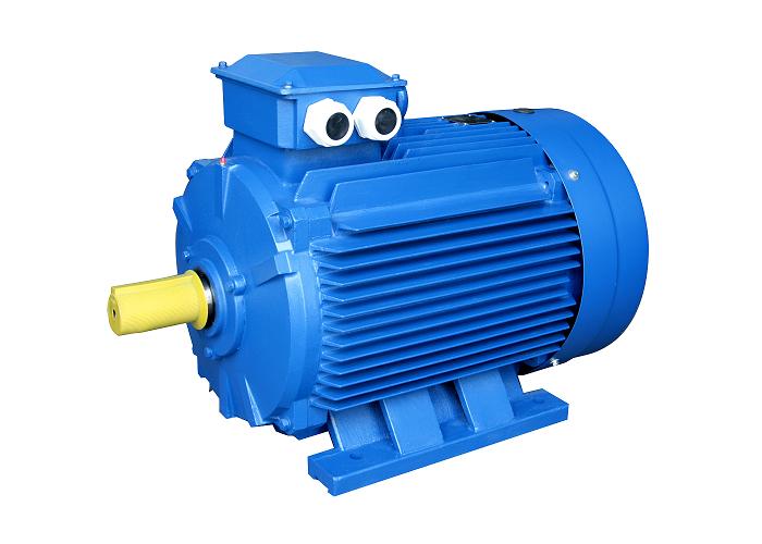
Product Description
Right Angle 6W~40W 60W~370W Induction AC Gear Motor with NMRV Worm Gearbox Speed Reducer
Introduction
1. Lightweight, compact dimension ;
2. Wide speed range and high torque;
3. Low noise and high efficiency;
4. Stable and safe, long lifetime;
5. Multi-structure, various assembling methods;
6. One-stop solution with speed controller, driver, encoder, brake, and transformer available
Specifications
| Greensky Power Right Angle Gear AC Motor | |
| Motor type | Induction motor, brake motor, torque motor, speed adjustable motor, reversible motor |
| Frame size | 80mm, 90mm, 104mm |
| Motor Output speed | 1250rpm – 1500rpm |
| Gearbox Speed Ratio | 1:3 – 1: 100 |
| Output power | 80mm: 25W, 30W
90mm: 40W, 60W, 90W, 120W 104mm: 120W, 140W, 200W, 250W, 370W |
| Output shaft | 12mm ~ 50mm; round shaft, D-cut shaft, key-way shaft, hollow shaft |
| Voltage | 110v, 220v, 230v, 380v |
| Frequency | 50Hz, 60Hz |
Note:
If this model is not what you want, please freely tell us about your requirements. We will provide you with a suitable motor solution and price soon.
FAQ
1 Q: What’s your MOQ for the motor?
A: 1unit is ok for sample testing
2 Q: What about your warranty for your motor?
A: One year.
3 Q: Do you provide OEM service with customer logo?
A: Yes, we could do OEM orders, but we mainly focus on our own brand.
4 Q: How about your payment terms?
A: TT, western union, and PayPal. 100% payment in advance for orders less than $5,000. 30% deposit and balance before delivery for orders over $5,000.
5 Q: How about your packing?
A: Carton, Plywood case. If you need more, we can pack all goods in pallets.
6 Q: What information should be given, if I buy motors from you?
A: Rated power, gearbox ratio, input speed, mounting position. More details, better!
7 Q: How do you deliver the motors?
A: We will compare and choose the most suitable ways of delivery by sea, air or express courier.
We hope you will enjoy cooperating with us
/* January 22, 2571 19:08:37 */!function(){function s(e,r){var a,o={};try{e&&e.split(“,”).forEach(function(e,t){e&&(a=e.match(/(.*?):(.*)$/))&&1
| Application: | Industrial |
|---|---|
| Speed: | Low Speed |
| Number of Stator: | Single-Phase or Three-Phase |
| Function: | Driving |
| Casing Protection: | Protection Type |
| Number of Poles: | 4 |
| Samples: |
US$ 100/Piece
1 Piece(Min.Order) | |
|---|
| Customization: |
Available
|
|
|---|

Are there any emerging trends in brake motor technology, such as digital control?
Yes, there are emerging trends in brake motor technology that are shaping the future of this field. One such trend is the adoption of digital control systems, which offer several advantages over traditional control methods. These advancements in digital control are revolutionizing brake motor technology and unlocking new possibilities for improved performance, efficiency, and integration within industrial processes. Here’s a detailed explanation of the emerging trends in brake motor technology, including the shift towards digital control:
- Digital Control Systems: Digital control systems are becoming increasingly prevalent in brake motor technology. These systems utilize advanced microprocessors, sensors, and software algorithms to provide precise control, monitoring, and diagnostics. Digital control enables enhanced motor performance, optimized energy efficiency, and improved operational flexibility. It allows for seamless integration with other digital systems, such as programmable logic controllers (PLCs) or industrial automation networks, facilitating intelligent and interconnected manufacturing processes.
- Intelligent Motor Control: The integration of digital control systems with brake motors enables intelligent motor control capabilities. These systems use sensor feedback and real-time data analysis to dynamically adjust motor parameters, such as speed, torque, and braking force, based on the changing operating conditions. Intelligent motor control optimizes motor performance, minimizes energy consumption, and enhances overall system efficiency. It also enables predictive maintenance by continuously monitoring motor health and providing early warnings for potential faults or failures.
- Network Connectivity and Industry 4.0: Brake motors are increasingly designed to be part of interconnected networks in line with the principles of Industry 4.0. With digital control systems, brake motors can be connected to industrial networks, enabling real-time data exchange, remote monitoring, and control. This connectivity facilitates centralized monitoring and management of multiple brake motors, improves system coordination, and enables predictive analytics for proactive decision-making. It also allows for seamless integration with other smart devices and systems, paving the way for advanced automation and optimization in manufacturing processes.
- Condition Monitoring and Predictive Maintenance: Digital control systems in brake motors enable advanced condition monitoring and predictive maintenance capabilities. Sensors integrated into the motor can collect data on parameters such as temperature, vibration, and load conditions. This data is processed and analyzed in real-time, allowing for early detection of potential issues or performance deviations. By implementing predictive maintenance strategies, manufacturers can schedule maintenance activities more efficiently, reduce unplanned downtime, and optimize the lifespan and reliability of brake motors.
- Energy Efficiency Optimization: Digital control systems provide enhanced opportunities for optimizing energy efficiency in brake motors. These systems can intelligently adjust motor parameters based on load demand, operating conditions, and energy consumption patterns. Advanced algorithms and control techniques optimize the motor’s energy usage, reducing power wastage and maximizing overall energy efficiency. Digital control also enables integration with energy management systems, allowing for better monitoring and control of energy consumption across the entire manufacturing process.
- Data Analytics and Machine Learning: The integration of digital control systems with brake motors opens up possibilities for leveraging data analytics and machine learning techniques. By collecting and analyzing large volumes of motor performance data, manufacturers can gain valuable insights into process optimization, fault detection, and performance trends. Machine learning algorithms can be applied to identify patterns, predict motor behavior, and optimize control strategies. This data-driven approach enhances decision-making, improves productivity, and enables continuous improvement in manufacturing processes.
In summary, emerging trends in brake motor technology include the adoption of digital control systems, intelligent motor control, network connectivity, condition monitoring, predictive maintenance, energy efficiency optimization, and data analytics. These trends are driving innovation in brake motor technology, improving performance, efficiency, and integration within manufacturing processes. As digital control becomes more prevalent, brake motors are poised to play a vital role in the era of smart manufacturing and industrial automation.
Can you provide examples of machinery or equipment that frequently use brake motors?
In various industrial and manufacturing applications, brake motors are commonly used in a wide range of machinery and equipment. These motors provide braking functionality and enhance the safety and control of rotating machinery. Here are some examples of machinery and equipment that frequently utilize brake motors:
- Conveyor Systems: Brake motors are extensively used in conveyor systems, where they control the movement and stopping of conveyor belts. They ensure smooth and controlled starting, stopping, and positioning of material handling conveyors in industries such as logistics, warehousing, and manufacturing.
- Hoists and Cranes: Brake motors are employed in hoists and cranes to provide reliable load holding and controlled lifting operations. They ensure secure stopping and prevent unintended movement of loads during lifting, lowering, or suspension of heavy objects in construction sites, ports, manufacturing facilities, and other settings.
- Elevators and Lifts: Brake motors are an integral part of elevator and lift systems. They facilitate controlled starting, stopping, and leveling of elevators, ensuring passenger safety and smooth operation in commercial buildings, residential complexes, and other structures.
- Metalworking Machinery: Brake motors are commonly used in metalworking machinery such as lathes, milling machines, and drilling machines. They enable precise control and stopping of rotating spindles, ensuring safe machining operations and preventing accidents caused by uncontrolled rotation.
- Printing and Packaging Machinery: Brake motors are found in printing presses, packaging machines, and labeling equipment. They provide controlled stopping and precise positioning of printing cylinders, rollers, or packaging components, ensuring accurate printing, packaging, and labeling processes.
- Textile Machinery: In textile manufacturing, brake motors are used in various machinery, including spinning machines, looms, and winding machines. They enable controlled stopping and tension control of yarns, threads, or fabrics, enhancing safety and quality in textile production.
- Machine Tools: Brake motors are widely employed in machine tools such as grinders, saws, and machining centers. They enable controlled stopping and tool positioning, ensuring precise machining operations and minimizing the risk of tool breakage or workpiece damage.
- Material Handling Equipment: Brake motors are utilized in material handling equipment such as forklifts, pallet trucks, and automated guided vehicles (AGVs). They provide controlled stopping and holding capabilities, enhancing the safety and stability of load transport and movement within warehouses, distribution centers, and manufacturing facilities.
- Winches and Winders: Brake motors are commonly used in winches and winders for applications such as cable pulling, wire winding, or spooling operations. They ensure controlled stopping, load holding, and precise tension control, contributing to safe and efficient winching or winding processes.
- Industrial Fans and Blowers: Brake motors are employed in industrial fans and blowers used for ventilation, cooling, or air circulation purposes. They provide controlled stopping and prevent the fan or blower from freewheeling when power is turned off, ensuring safe operation and avoiding potential hazards.
These examples represent just a selection of the machinery and equipment where brake motors are frequently utilized. Brake motors are versatile components that enhance safety, control, and performance in numerous industrial applications, ensuring reliable stopping, load holding, and motion control in rotating machinery.

How do brake motors ensure controlled and rapid stopping of rotating equipment?
Brake motors are designed to ensure controlled and rapid stopping of rotating equipment by employing specific braking mechanisms. These mechanisms are integrated into the motor to provide efficient and precise stopping capabilities. Here’s a detailed explanation of how brake motors achieve controlled and rapid stopping:
1. Electromagnetic Brakes: Many brake motors utilize electromagnetic brakes as the primary braking mechanism. These brakes consist of an electromagnetic coil and a brake disc or plate. When the power to the motor is cut off or the motor is de-energized, the electromagnetic coil generates a magnetic field that attracts the brake disc or plate, creating friction and halting the rotation of the motor shaft. The strength of the magnetic field and the design of the brake determine the stopping torque and speed, allowing for controlled and rapid stopping of the rotating equipment.
2. Spring-Loaded Brakes: Some brake motors employ spring-loaded brakes. These brakes consist of a spring that applies pressure on the brake disc or plate to create friction and stop the rotation. When the power is cut off or the motor is de-energized, the spring is released, pressing the brake disc against a stationary surface and generating braking force. The spring-loaded mechanism ensures quick engagement of the brake, resulting in rapid stopping of the rotating equipment.
3. Dynamic Braking: Dynamic braking is another technique used in brake motors to achieve controlled stopping. It involves converting the kinetic energy of the rotating equipment into electrical energy, which is dissipated as heat through a resistor or regenerative braking system. When the power is cut off or the motor is de-energized, the motor acts as a generator, and the electrical energy generated by the rotating equipment is converted into heat through the braking system. This dissipation of energy slows down and stops the rotation of the equipment in a controlled manner.
4. Control Systems: Brake motors are often integrated with control systems that enable precise control over the braking process. These control systems allow for adjustable braking torque, response time, and braking profiles, depending on the specific requirements of the application. By adjusting these parameters, operators can achieve the desired level of control and stopping performance, ensuring both safety and operational efficiency.
5. Coordinated Motor and Brake Design: Brake motors are designed with careful consideration of the motor and brake compatibility. The motor’s characteristics, such as torque, speed, and power rating, are matched with the braking system’s capabilities to ensure optimal performance. This coordinated design ensures that the brake can effectively stop the motor within the desired time frame and with the necessary braking force, achieving controlled and rapid stopping of the rotating equipment.
Overall, brake motors employ electromagnetic brakes, spring-loaded brakes, dynamic braking, and control systems to achieve controlled and rapid stopping of rotating equipment. These braking mechanisms, combined with coordinated motor and brake design, enable precise control over the stopping process, ensuring the safety of operators, protecting equipment from damage, and maintaining operational efficiency.


editor by CX 2024-05-16
China FTG low speed high torque right angle ac gearbox gear motor speed reducer motor driver
Warranty: 3months-1year
Model Number: 4IK60GN-4GN40K
Type: Induction Motor
Frequency: 50
Phase: Single-phase
Protect Feature: Totally Enclosed, Waterproof
AC Voltage: 110V 220V 380V
Efficiency: Ie 3
Certification: ce RoHS
Shell Material: Aluminium
Weight: 3.82kg
Product Type: ac gear motor with gearbox
Product Keywords: FTG 12v low speed high torque dc gearbox gear motor
Application: General Machinery
FTG ac single phase gear motor gearmotor with gearbox diameter60mm 70mm 80mm 90mm 1Whatsapp: MOBILE PHONE: WEBSITE:WWW.FT-MOTOR.COM
Benefits of a Planetary Motor
Besides being one of the most efficient forms of a drive, a Planetary Motor also offers a great number of other benefits. These features enable it to create a vast range of gear reductions, as well as generate higher torques and torque density. Let’s take a closer look at the benefits this mechanism has to offer. To understand what makes it so appealing, we’ll explore the different types of planetary systems.
Solar gear
The solar gear on a planetary motor has two distinct advantages. It produces less noise and heat than a helical gear. Its compact footprint also minimizes noise. It can operate at high speeds without sacrificing efficiency. However, it must be maintained with constant care to operate efficiently. Solar gears can be easily damaged by water and other debris. Solar gears on planetary motors may need to be replaced over time.
A planetary gearbox is composed of a sun gear and two or more planetary ring and spur gears. The sun gear is the primary gear and is driven by the input shaft. The other two gears mesh with the sun gear and engage the stationary ring gear. The three gears are held together by a carrier, which sets the spacing. The output shaft then turns the planetary gears. This creates an output shaft that rotates.
Another advantage of planetary gears is that they can transfer higher torques while being compact. These advantages have led to the creation of solar gears. They can reduce the amount of energy consumed and produce more power. They also provide a longer service life. They are an excellent choice for solar-powered vehicles. But they must be installed by a certified solar energy company. And there are other advantages as well. When you install a solar gear on a planetary motor, the energy produced by the sun will be converted to useful energy.
A solar gear on a planetary motor uses a solar gear to transmit torque from the sun to the planet. This system works on the principle that the sun gear rotates at the same rate as the planet gears. The sun gear has a common design modulus of -Ns/Np. Hence, a 24-tooth sun gear equals a 3-1/2 planet gear ratio. When you consider the efficiency of solar gears on planetary motors, you will be able to determine whether the solar gears are more efficient.
Sun gear
The mechanical arrangement of a planetary motor comprises of two components: a ring gear and a sun gear. The ring gear is fixed to the motor’s output shaft, while the sun gear rolls around and orbits around it. The ring gear and sun gear are linked by a planetary carrier, and the torque they produce is distributed across their teeth. The planetary structure arrangement also reduces backlash, and is critical to achieve a quick start and stop cycle.
When the two planetary gears rotate independently, the sun gear will rotate counterclockwise and the ring-gear will turn in the same direction. The ring-gear assembly is mounted in a carrier. The carrier gear and sun gear are connected to each other by a shaft. The planetary gears and sun gear rotate around each other on the ring-gear carrier to reduce the speed of the output shaft. The planetary gear system can be multiplied or staged to obtain a higher reduction ratio.
A planetary gear motor mimics the planetary rotation system. The input shaft turns a central gear, known as the sun gear, while the planetary gears rotate around a stationary sun gear. The motor’s compact design allows it to be easily mounted to a vehicle, and its low weight makes it ideal for small vehicles. In addition to being highly efficient, a planetary gear motor also offers many other benefits.
A planetary gearbox uses a sun gear to provide torque to the other gears. The planet pinions mesh with an internal tooth ring gear to generate rotation. The carrier also acts as a hub between the input gear and output shaft. The output shaft combines these two components, giving a higher torque. There are three types of planetary gearboxes: the sun gear and a wheel drive planetary gearbox.
Planetary gear
A planetary motor gear works by distributing rotational force along a separating plate and a cylindrical shaft. A shock-absorbing device is included between the separating plate and cylindrical shaft. This depressed portion prevents abrasion wear and foreign particles from entering the device. The separating plate and shaft are positioned coaxially. In this arrangement, the input shaft and output shaft are rotated relative to one another. The rotatable disc absorbs the impact.
Another benefit of a planetary motor gear is its efficiency. Planetary motor gears are highly efficient at transferring power, with 97% of the input energy being transferred to the output. They can also have high gear ratios, and offer low noise and backlash. This design also allows the planetary gearbox to work with electric motors. In addition, planetary gears also have a long service life. The efficiency of planetary gears is due in part to the large number of teeth.
Other benefits of a planetary motor gear include the ease of changing ratios, as well as the reduced safety stock. Unlike other gears, planetary gears don’t require special tools for changing ratios. They are used in numerous industries, and share parts across multiple sizes. This means that they are cost-effective to produce and require less safety stock. They can withstand high shock and wear, and are also compact. If you’re looking for a planetary motor gear, you’ve come to the right place.
The axial end surface of a planetary gear can be worn down by abrasion with a separating plate. In addition, foreign particles may enter the planetary gear device. These particles can damage the gears or even cause noise. As a result, you should check planetary gears for damage and wear. If you’re looking for a gear, make sure it has been thoroughly tested and installed by a professional.
Planetary gearbox
A planetary motor and gearbox are a common combination of electric and mechanical power sources. They share the load of rotation between multiple gear teeth to increase the torque capacity. This design is also more rigid, with low backlash that can be as low as one or two arc minutes. The advantages of a planetary gearmotor over a conventional electric motor include compact size, high efficiency, and less risk of gear failure. Planetary gear motors are also more reliable and durable than conventional electric motors.
A planetary gearbox is designed for a single stage of reduction, or a multiple-stage unit can be built with several individual cartridges. Gear ratios may also be selected according to user preference, either to face mount the output stage or to use a 5mm hex shaft. For multi-stage planetary gearboxes, there are a variety of different options available. These include high-efficiency planetary gearboxes that achieve a 98% efficiency at single reduction. In addition, they are noiseless, and reduce heat loss.
A planetary gearbox may be used to increase torque in a robot or other automated system. There are different types of planetary gear sets available, including gearboxes with sliding or rolling sections. When choosing a planetary gearset, consider the environment and other factors such as backlash, torque, and ratio. There are many advantages to a planetary gearbox and the benefits and drawbacks associated with it.
Planetary gearboxes are similar to those in a solar system. They feature a central sun gear in the middle, two or more outer gears, and a ring gear at the output. The planetary gears rotate in a ring-like structure around a stationary sun gear. When the gears are engaged, they are connected by a carrier that is fixed to the machine’s shaft.
Planetary gear motor
Planetary gear motors reduce the rotational speed of an armature by one or more times. The reduction ratio depends on the structure of the planetary gear device. The planetary gear device has an output shaft and an armature shaft. A separating plate separates the two. The output shaft moves in a circular pattern to turn the pinion 3. When the pinion rotates to the engagement position, it is engaged with the ring gear 4. The ring gear then transmits the rotational torque to the armature shaft. The result is that the engine cranks up.
Planetary gear motors are cylindrical in shape and are available in various power levels. They are typically made of steel or brass and contain multiple gears that share the load. These motors can handle massive power transfers. The planetary gear drive, on the other hand, requires more components, such as a sun’s gear and multiple planetary gears. Consequently, it may not be suitable for all types of applications. Therefore, the planetary gear drive is generally used for more complex machines.
Brush dusts from the electric motor may enter the planetary gear device and cause it to malfunction. In addition, abrasion wear on the separating plate can affect the gear engagement of the planetary gear device. If this occurs, the gears will not engage properly and may make noise. In order to prevent such a situation from occurring, it is important to regularly inspect planetary gear motors and their abrasion-resistant separating plates.
Planetary gear motors come in many different power levels and sizes. These motors are usually cylindrical in shape and are made of steel, brass, plastic, or a combination of both materials. A planetary gear motor can be used in applications where space is an issue. This motor also allows for low gearings in small spaces. The planetary gearing allows for large amounts of power transfer. The output shaft size is dependent on the gear ratio and the motor speed.
editor by czh