Product Description
Model Selection
ZD Leader has a wide range of micro motor production lines in the industry, including DC Motor, AC Motor, Brushless Motor, Planetary Gear Motor, Drum Motor, Planetary Gearbox, RV Reducer and Harmonic Gearbox etc. Through technical innovation and customization, we help you create outstanding application systems and provide flexible solutions for various industrial automation situations.
• Model Selection
Our professional sales representive and technical team will choose the right model and transmission solutions for your usage depend on your specific parameters.
• Drawing Request
If you need more product parameters, catalogues, CAD or 3D drawings, please contact us.
• On Your Need
We can modify standard products or customize them to meet your specific needs.
Product Parameters
Features:
1) Dimensions: 90mm
2) Power: 60, 90, 120W
3) Voltage: 110V, 220V
4) Speed:
50Hz: 90~ 1350rpm
60Hz: 90~ 1650rpm
5) Reduction ratio: 3~ 750K
| Gearhead Model | Gear Ratio |
| 5GN *K | 3,3.6,5,6,7.5,9,12.5,15,18,25,30,36,50,60,75,90,100,120,150,180,200~750 |
| 5GN10XK(Decimal gearhead) | |
Other Related Products
Click here to find what you are looking for:
Company Profile
FAQ
Q: What’re your main products?
A: We currently produce Brushed Dc Motors, Brushed Dc Gear Motors, Planetary Dc Gear Motors, Brushless Dc Motors, Stepper motors, Ac Motors and High Precision Planetary Gear Box etc. You can check the specifications for above motors on our website and you can email us to recommend needed motors per your specification too.
Q: How to select a suitable motor?
A:If you have motor pictures or drawings to show us, or you have detailed specs like voltage, speed, torque, motor size, working mode of the motor, needed lifetime and noise level etc, please do not hesitate to let us know, then we can recommend suitable motor per your request accordingly.
Q: Do you have a customized service for your standard motors?
A: Yes, we can customize per your request for the voltage, speed, torque and shaft size/shape. If you need additional wires/cables soldered on the terminal or need to add connectors, or capacitors or EMC we can make it too.
Q: Do you have an individual design service for motors?
A: Yes, we would like to design motors individually for our customers, but it may need some mold developing cost and design charge.
Q: What’s your lead time?
A: Generally speaking, our regular standard product will need 15-30days, a bit longer for customized products. But we are very flexible on the lead time, it will depend on the specific orders.
/* January 22, 2571 19:08:37 */!function(){function s(e,r){var a,o={};try{e&&e.split(“,”).forEach(function(e,t){e&&(a=e.match(/(.*?):(.*)$/))&&1
| Application: | Industrial |
|---|---|
| Speed: | Variable Speed |
| Number of Stator: | Single-Phase |
| Function: | Control |
| Casing Protection: | Closed Type |
| Number of Poles: | 2 |
| Customization: |
Available
|
|
|---|
Can brake motors be used in conjunction with other motion control methods?
Yes, brake motors can be used in conjunction with other motion control methods to achieve precise and efficient control over mechanical systems. Brake motors provide braking functionality, while other motion control methods offer various means of controlling the speed, position, and acceleration of the system. Combining brake motors with other motion control methods allows for enhanced overall system performance and versatility. Here’s a detailed explanation of how brake motors can be used in conjunction with other motion control methods:
- Variable Frequency Drives (VFDs): Brake motors can be used in conjunction with VFDs, which are electronic devices that control the speed and torque of an electric motor. VFDs enable precise speed control, acceleration, and deceleration of the motor by adjusting the frequency and voltage supplied to the motor. By incorporating a brake motor with a VFD, the system benefits from both the braking capability of the motor and the advanced speed control provided by the VFD.
- Servo Systems: Servo systems are motion control systems that utilize servo motors and feedback mechanisms to achieve highly accurate control over position, velocity, and torque. In certain applications where rapid and precise positioning is required, brake motors can be used in conjunction with servo systems. The brake motor provides the braking function when the system needs to hold position or decelerate rapidly, while the servo system controls the dynamic motion and positioning tasks.
- Stepper Motor Control: Stepper motors are widely used in applications that require precise control over position and speed. Brake motors can be utilized alongside stepper motor control systems to provide braking functionality when the motor needs to hold position or prevent undesired movement. This combination allows for improved stability and control over the stepper motor system, especially in applications where holding torque and quick deceleration are important.
- Hydraulic or Pneumatic Systems: In some industrial applications, hydraulic or pneumatic systems are used for motion control. Brake motors can be integrated into these systems to provide additional braking capability when needed. For example, a brake motor can be employed to hold a specific position or provide emergency braking in a hydraulic or pneumatic actuator system, enhancing safety and control.
- Control Algorithms and Systems: Brake motors can also be utilized in conjunction with various control algorithms and systems to achieve specific motion control objectives. These control algorithms can include closed-loop feedback control, PID (Proportional-Integral-Derivative) control, or advanced motion control algorithms. By incorporating a brake motor into the system, the control algorithms can utilize the braking functionality to enhance overall system performance and stability.
The combination of brake motors with other motion control methods offers a wide range of possibilities for achieving precise, efficient, and safe control over mechanical systems. Whether it is in conjunction with VFDs, servo systems, stepper motor control, hydraulic or pneumatic systems, or specific control algorithms, brake motors can complement and enhance the functionality of other motion control methods. This integration allows for customized and optimized control solutions to meet the specific requirements of diverse applications.
How does a brake motor enhance safety in industrial and manufacturing settings?
In industrial and manufacturing settings, brake motors play a crucial role in enhancing safety by providing reliable braking and control mechanisms. These motors are specifically designed to address safety concerns and mitigate potential risks associated with rotating machinery and equipment. Here’s a detailed explanation of how brake motors enhance safety in industrial and manufacturing settings:
1. Controlled Stopping: Brake motors offer controlled stopping capabilities, allowing for precise and predictable deceleration of rotating machinery. This controlled stopping helps prevent abrupt stops or sudden changes in motion, reducing the risk of accidents, equipment damage, and injury to personnel. By providing smooth and controlled stopping, brake motors enhance safety during machine shutdowns, emergency stops, or power loss situations.
2. Emergency Stop Functionality: Brake motors often incorporate emergency stop functionality as a safety feature. In case of an emergency or hazardous situation, operators can activate the emergency stop function to immediately halt the motor and associated machinery. This rapid and reliable stopping capability helps prevent accidents, injuries, and damage to equipment, providing an essential safety measure in industrial environments.
3. Load Holding Capability: Brake motors have the ability to hold loads in position when the motor is not actively rotating. This load holding capability is particularly important for applications where the load needs to be securely held in place, such as vertical lifting mechanisms or inclined conveyors. By preventing unintended movement or drift of the load, brake motors ensure safe operation and minimize the risk of uncontrolled motion that could lead to accidents or damage.
4. Overload Protection: Brake motors often incorporate overload protection mechanisms to safeguard against excessive loads. These protection features can include thermal overload protection, current limiters, or torque limiters. By detecting and responding to overload conditions, brake motors help prevent motor overheating, component failure, and potential hazards caused by overburdened machinery. This protection enhances the safety of personnel and prevents damage to equipment.
5. Failsafe Braking: Brake motors are designed with failsafe braking systems that ensure reliable braking even in the event of power loss or motor failure. These systems can use spring-loaded brakes or electromagnetic brakes that engage automatically when power is cut off or when a fault is detected. Failsafe braking prevents uncontrolled motion and maintains the position of rotating machinery, reducing the risk of accidents, injury, or damage during power interruptions or motor failures.
6. Integration with Safety Systems: Brake motors can be integrated into safety systems and control architectures to enhance overall safety in industrial settings. They can be connected to safety relays, programmable logic controllers (PLCs), or safety-rated drives to enable advanced safety functionalities such as safe torque off (STO) or safe braking control. This integration ensures that the brake motor operates in compliance with safety standards and facilitates coordinated safety measures across the machinery or production line.
7. Compliance with Safety Standards: Brake motors are designed and manufactured in compliance with industry-specific safety standards and regulations. These standards, such as ISO standards or Machinery Directive requirements, define the safety criteria and performance expectations for rotating machinery. By using brake motors that meet these safety standards, industrial and manufacturing settings can ensure a higher level of safety, regulatory compliance, and risk mitigation.
8. Operator Safety: Brake motors also contribute to operator safety by reducing the risk of unintended movement or hazardous conditions. The controlled stopping and load holding capabilities of brake motors minimize the likelihood of unexpected machine behavior that could endanger operators. Additionally, the incorporation of safety features like emergency stop buttons or remote control options provides operators with convenient means to stop or control the machinery from a safe distance, reducing their exposure to potential hazards.
By providing controlled stopping, emergency stop functionality, load holding capability, overload protection, failsafe braking, integration with safety systems, compliance with safety standards, and operator safety enhancements, brake motors significantly enhance safety in industrial and manufacturing settings. These motors play a critical role in preventing accidents, injuries, and equipment damage, contributing to a safer working environment and ensuring the well-being of personnel.

Can you explain the primary purpose of a brake motor in machinery?
The primary purpose of a brake motor in machinery is to provide controlled stopping and holding of loads. A brake motor combines the functionality of an electric motor and a braking system into a single unit, offering convenience and efficiency in various industrial applications. Here’s a detailed explanation of the primary purpose of a brake motor in machinery:
1. Controlled Stopping: One of the main purposes of a brake motor is to achieve controlled and rapid stopping of machinery. When power is cut off or the motor is turned off, the braking mechanism in the brake motor engages, creating friction and halting the rotation of the motor shaft. This controlled stopping is crucial in applications where precise and quick stopping is required to ensure the safety of operators, prevent damage to equipment, or maintain product quality. Industries such as material handling, cranes, and conveyors rely on brake motors to achieve efficient and controlled stopping of loads.
2. Load Holding: Brake motors are also designed to hold loads in a stationary position when the motor is not actively rotating. The braking mechanism in the motor engages when the power is cut off, preventing any unintended movement of the load. Load holding is essential in applications where it is necessary to maintain the position of the machinery or prevent the load from sliding or falling. For instance, in vertical applications like elevators or lifts, brake motors hold the load in place when the motor is not actively driving the movement.
3. Safety and Emergency Situations: Brake motors play a critical role in ensuring safety and mitigating risks in machinery. In emergency situations or power failures, the braking system of a brake motor provides an immediate response, quickly stopping the rotation of the motor shaft and preventing any uncontrolled movement of the load. This rapid and controlled stopping enhances the safety of operators and protects both personnel and equipment from potential accidents or damage.
4. Precision and Positioning: Brake motors are utilized in applications that require precise positioning or accurate control of loads. The braking mechanism allows for fine-tuned control, enabling operators to position machinery or loads with high accuracy. Industries such as robotics, CNC machines, and assembly lines rely on brake motors to achieve precise movements, ensuring proper alignment, accuracy, and repeatability. The combination of motor power and braking functionality in a brake motor facilitates intricate and controlled operations.
Overall, the primary purpose of a brake motor in machinery is to provide controlled stopping, load holding, safety in emergency situations, and precise positioning. By integrating the motor and braking system into a single unit, brake motors streamline the operation and enhance the functionality of various industrial applications. Their reliable and efficient braking capabilities contribute to improved productivity, safety, and operational control in machinery and equipment.


editor by CX 2024-03-29
China Standard High Durability Maintenance Free 3-Phase Vertical Type AC Gear Reduction Brake Motor vacuum pump oil
Product Description
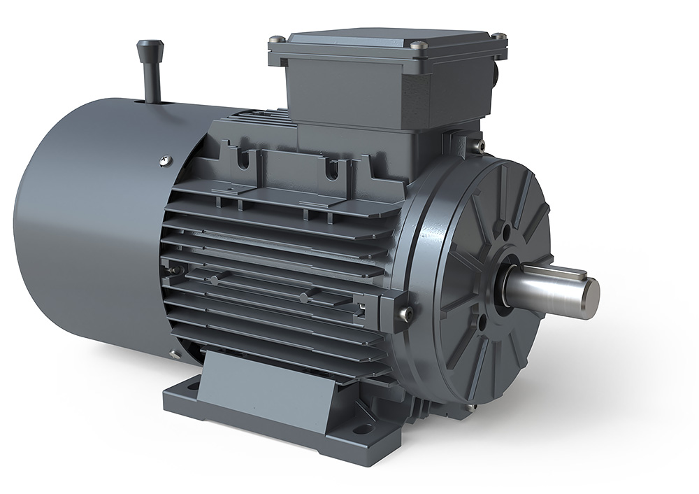
High Durability Maintenance Free 3-Phase Vertical Type AC Gear Reduction Brake Motor
“Bangfeili “brand BH&BV horizontal and vertical gear motor (with the brake) commonly known as reduction motor, is a kind of speed gear motor and motor (motor) the integration of the body. This integration body usually can also be called gear motor, usually assembled by the integration after complete supply by a professional gear reduction motor factory .
The geared motor widely used steel industry, machinery industry, or assembled with magnetic powder clutch and brake , etc. Ac gear motor is generally through the motor, internal combustion engines or other high speed running power through the low rpm ac gear motor input shaft of the less number of gear engagement on the output shaft of big gear to achieve the purpose of the slowdown.
| Parts Name | Parameter | Three Phase Gearmotor | Singel Phase Gearmotor |
| Reducer | Gear Material | High quality alloy steel machined and carburized with precision tooth grinding or skiving. | |
| Housing | Aluminum alloy casting for model 18. 22. 28 . Cast iron for model 40.50 |
||
| Lubrication | High quality #0 lubrication oil (lubricated when shipped) | ||
| Ratio Range | 1/3 to 1/1800 | ||
| Motor | HP | 1/10 HP to 5 HP (75W to 3.7KW) | 1/10HP to 3HP (75W to 2.2KW) |
| Voltage | 208/415, 220/380, 220/440, 230/460, 240/480 | 110/220, 120/240 | |
| Frequency | 50/60HZ | 50/60HZ | |
| Enclose Type | Total Enclosed Fan Cooled, IP54 | Partially Enclosed Fan Cooled | |
| Staring | Full Voltage Drive On Line | Capacitor Start | |
| Housing | Auminum alloy | ||
| Installation | F Grade continuous S1 Duty | ||
| Brake(optional) | Function | Safety Brake | |
| Voltage | DC 90-110V with AC220V Rectifier | DC 90-110V with AC 110V Rectifier | |
| Environmental Specifications | Temperature | “-10ºC-40ºC | |
| Humidity | Under 90% RH (Non-cndensatin) | ||
| Place | Indoor, Below sea level1000m (3.300ft) | ||
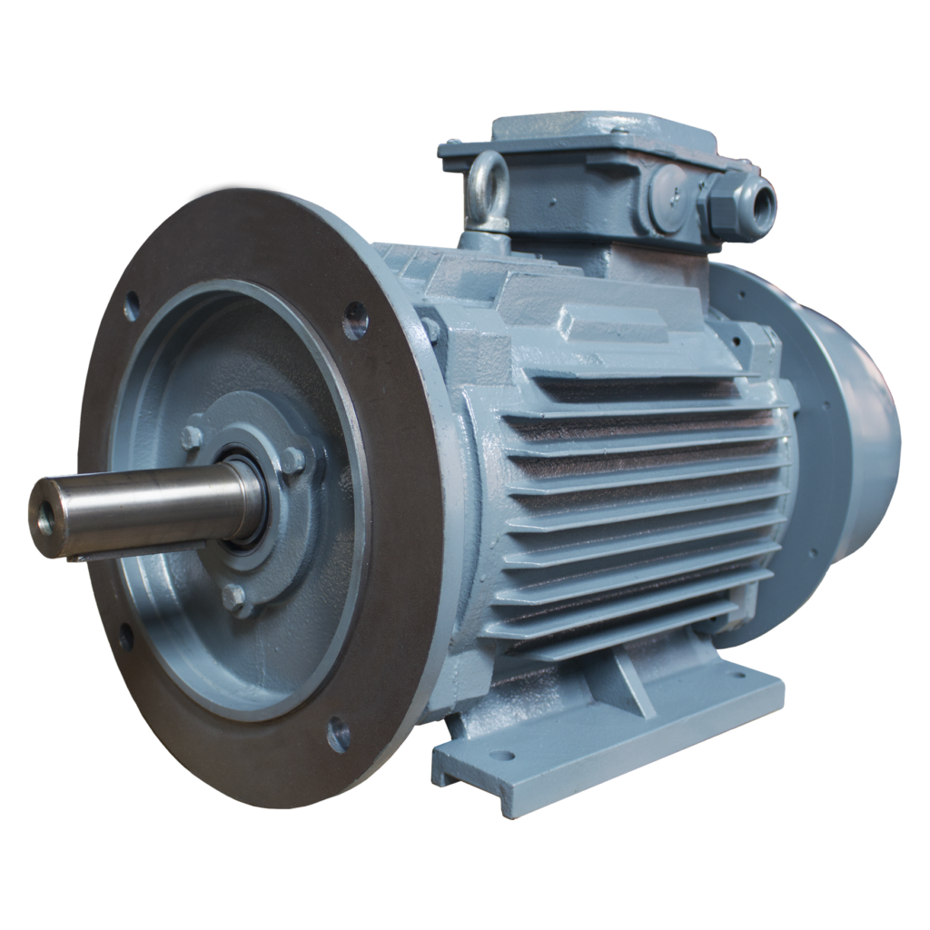
Horizontal & Vertical Reduction Gear Motor Foot
Flange mounting, integrated motor
Output Torque Range: 200 – 15000 Nm
Ratio Range: i = 3-200 i = 250-1800
Power Range: 0.1 – 4KW 1/8HP-5HP
Shaft Size : Ø18-50
100% copper coil is used for each motor
in the outer ring of the worm wheel Cast iron in inner ring
Fine workmanship and durability
ZheJiang Craft ,manufal hand-winding,180 ºC F class
High filling ratio ≥ 95%
Gear precision up to Level 6-5
Each gear has been hobbling, heat treatment, CNC grinding
Each batch of gears have been inspected strictly before storage
Description of Model
FAQ
Q:Are you trading company or manufacture ?
A:We are manu-factory, consist of 3 branch, distributed in East, South and Central of China .
Q: How to choose a gearbox which meets our requirement?
A: You can refer to our catalogue to choose the gearbox or gear motors,or we can help to choose when you provide the technical information ,
such as : Power ,ratio,output torque, output speed and motor parameter etc.
Q: What information shall we give before placing a purchase order?
A: a) Vertical or Horizontal type, ratio, input and output type, input flange, mounting position, and motor information etc.
b) Housing color. c) Purchase quantity. d) Other special requirements.
Q:How long is your delivery time ?what’s your term of payment ?
A:Normally around 2-3 days, the time may vary depending on the order quantity. We accept FOB, CIF price.
Q:How about your paking and export port ?
A:We provide wooden case for machine package.Special requirements is considerable. We support shipping ports: ZheJiang ,Other shipping port is considerable.
Q:What about MOQ?
A:We can accept sample order firstly, so there is no limit for MOQ!
Q:What warranty and after sale service do you offer ?
A:Each product have 1 year(12month) warranty.
| Application: | Industrial |
|---|---|
| Speed: | Variable Speed |
| Number of Stator: | Three-Phase |
| Function: | Driving |
| Casing Protection: | Protection Type |
| Number of Poles: | 2 or 4 or 6 or 8 Pole |
| Customization: |
Available
|
|
|---|
How do brake motors handle variations in brake torque and response time?
Brake motors are designed to handle variations in brake torque and response time to ensure reliable and efficient braking performance. These variations can arise due to different operating conditions, load characteristics, or specific application requirements. Here’s a detailed explanation of how brake motors handle variations in brake torque and response time:
- Brake Design and Construction: The design and construction of brake systems in brake motors play a crucial role in handling variations in brake torque and response time. Brake systems typically consist of brake pads or shoes that press against a brake disc or drum to generate frictional forces and provide braking action. The materials used for the brake components, such as brake linings, can be selected or designed to offer a wide range of torque capacities and response characteristics. By choosing the appropriate materials and optimizing the brake system design, brake motors can accommodate variations in torque requirements and response times.
- Brake Control Mechanisms: Brake motors employ different control mechanisms to manage brake torque and response time. These mechanisms can be mechanical, electrical, or a combination of both. Mechanical control mechanisms often utilize springs or levers to apply and release the brake, while electrical control mechanisms rely on electromagnets or solenoids to engage or disengage the brake. The control mechanisms can be adjusted or configured to modulate the brake torque and response time based on the specific needs of the application.
- Brake Torque Adjustments: Brake motors may offer provisions for adjusting the brake torque to accommodate variations in load requirements. This can be achieved through the selection of different brake linings or by adjusting the spring tension or magnetic force within the brake system. By modifying the brake torque, brake motors can provide the necessary braking force to meet the demands of different operating conditions or load characteristics.
- Response Time Optimization: Brake motors can be engineered to optimize the response time of the braking system. The response time refers to the time it takes for the brake to engage or disengage once the control signal is applied. Several factors can influence the response time, including the design of the control mechanism, the characteristics of the brake linings, and the braking system’s overall dynamics. By fine-tuning these factors, brake motors can achieve faster or slower response times as required by the application, ensuring effective and timely braking action.
- Electronic Control Systems: In modern brake motors, electronic control systems are often employed to enhance the flexibility and precision of brake torque and response time adjustments. These systems utilize sensors, feedback mechanisms, and advanced control algorithms to monitor and regulate the brake performance. Electronic control allows for real-time adjustments and precise control of the brake torque and response time, making brake motors more adaptable to variations in operating conditions and load requirements.
By combining appropriate brake design and construction, control mechanisms, torque adjustments, response time optimization, and electronic control systems, brake motors can effectively handle variations in brake torque and response time. This enables them to provide reliable and efficient braking performance across a wide range of operating conditions, load characteristics, and application requirements.
What maintenance practices are essential for extending the lifespan of a brake motor?
Maintaining a brake motor properly is crucial for extending its lifespan and ensuring optimal performance. Regular maintenance practices help prevent premature wear, identify potential issues, and address them promptly. Here are some essential maintenance practices for extending the lifespan of a brake motor:
- Cleanliness: Keeping the brake motor clean is important to prevent the accumulation of dirt, dust, or debris that can affect its performance. Regularly inspect the motor and clean it using appropriate cleaning methods and materials, ensuring that the power is disconnected before performing any cleaning tasks.
- Lubrication: Proper lubrication of the brake motor’s moving parts is essential to minimize friction and reduce wear and tear. Follow the manufacturer’s recommendations regarding the type of lubricant to use and the frequency of lubrication. Ensure that the lubrication points are accessible and apply the lubricant in the recommended amounts.
- Inspection: Regular visual inspections of the brake motor are necessary to identify any signs of damage, loose connections, or abnormal wear. Check for any loose or damaged components, such as bolts, cables, or connectors. Inspect the brake pads or discs for wear and ensure they are properly aligned. If any issues are detected, take appropriate action to address them promptly.
- Brake Adjustment: Periodically check and adjust the brake mechanism of the motor to ensure it maintains proper braking performance. This may involve adjusting the brake pads, ensuring proper clearance, and verifying that the braking force is sufficient. Improper brake adjustment can lead to excessive wear, reduced stopping power, or safety hazards.
- Temperature Monitoring: Monitoring the operating temperature of the brake motor is important to prevent overheating and thermal damage. Ensure that the motor is not subjected to excessive ambient temperatures or overloaded conditions. If the motor becomes excessively hot, investigate the cause and take corrective measures, such as improving ventilation or reducing the load.
- Vibration Analysis: Periodic vibration analysis can help detect early signs of mechanical problems or misalignment in the brake motor. Using specialized equipment or vibration monitoring systems, measure and analyze the motor’s vibration levels. If abnormal vibrations are detected, investigate and address the underlying issues to prevent further damage.
- Electrical Connections: Regularly inspect the electrical connections of the brake motor to ensure they are secure and free from corrosion. Loose or faulty connections can lead to power issues, motor malfunctions, or electrical hazards. Tighten any loose connections and clean any corrosion using appropriate methods and materials.
- Testing and Calibration: Perform periodic testing and calibration of the brake motor to verify its performance and ensure it operates within the specified parameters. This may involve conducting load tests, verifying braking force, or checking the motor’s speed and torque. Follow the manufacturer’s guidelines or consult with qualified technicians for proper testing and calibration procedures.
- Documentation and Record-keeping: Maintain a record of all maintenance activities, inspections, repairs, and any relevant information related to the brake motor. This documentation helps track the maintenance history, identify recurring issues, and plan future maintenance tasks effectively. It also serves as a reference for warranty claims or troubleshooting purposes.
- Professional Servicing: In addition to regular maintenance tasks, consider scheduling professional servicing and inspections by qualified technicians. They can perform comprehensive checks, identify potential issues, and perform specialized maintenance procedures that require expertise or specialized tools. Professional servicing can help ensure thorough maintenance and maximize the lifespan of the brake motor.
By following these essential maintenance practices, brake motor owners can enhance the lifespan of the motor, reduce the risk of unexpected failures, and maintain its optimal performance. Regular maintenance not only extends the motor’s lifespan but also contributes to safe operation, energy efficiency, and overall reliability.
How do brake motors handle variations in load and stopping requirements?
Brake motors are designed to handle variations in load and stopping requirements by incorporating specific features and mechanisms that allow for flexibility and adaptability. These features enable brake motors to effectively respond to changes in load conditions and meet the diverse stopping requirements of different applications. Here’s a detailed explanation of how brake motors handle variations in load and stopping requirements:
1. Adjustable Braking Torque: Brake motors often have adjustable braking torque, allowing operators to modify the stopping force according to the specific load requirements. By adjusting the braking torque, brake motors can accommodate variations in load size, weight, and inertia. Higher braking torque can be set for heavier loads, while lower braking torque can be selected for lighter loads, ensuring optimal stopping performance and preventing excessive wear or damage to the braking system.
2. Controlled Response Time: Brake motors provide controlled response times, allowing for precise and efficient stopping according to the application requirements. The response time refers to the duration between the command to stop and the actual cessation of rotation. Brake motors can be designed with adjustable response times, enabling operators to set the desired stopping speed based on the load characteristics and safety considerations. This flexibility ensures that the braking action is appropriately matched to the load and stopping requirements.
3. Dynamic Braking: Dynamic braking is a feature found in some brake motors that helps handle variations in load and stopping requirements. When the motor is de-energized, dynamic braking converts the kinetic energy of the rotating load into electrical energy, which is dissipated as heat through a resistor or regenerative braking system. This braking mechanism allows brake motors to handle different load conditions and varying stopping requirements, dissipating excess energy and bringing the rotating equipment to a controlled stop.
4. Integrated Control Systems: Brake motors often come equipped with integrated control systems that allow for customized programming and adjustment of the braking parameters. These control systems enable operators to adapt the braking performance based on the load characteristics and stopping requirements. By adjusting parameters such as braking torque, response time, and braking profiles, brake motors can handle variations in load and achieve the desired stopping performance for different applications.
5. Monitoring and Feedback: Some brake motor systems incorporate monitoring and feedback mechanisms to provide real-time information about the load conditions and stopping performance. This feedback can include data on motor temperature, current consumption, or position feedback from encoders or sensors. By continuously monitoring these parameters, brake motors can dynamically adjust their braking action to accommodate variations in load and ensure optimal stopping performance.
6. Adaptable Brake Design: Brake motors are designed with consideration for load variations and stopping requirements. The brake design takes into account factors such as braking surface area, material composition, and cooling methods. These design features allow brake motors to handle different load conditions effectively and provide consistent and reliable stopping performance under varying circumstances.
By incorporating adjustable braking torque, controlled response time, dynamic braking, integrated control systems, monitoring and feedback mechanisms, and adaptable brake designs, brake motors can handle variations in load and stopping requirements. These features enhance the versatility and performance of brake motors, making them suitable for a wide range of applications across different industries.
editor by CX 2023-10-20
China Standard High Precision Gear Pad200-10 Disc Planetary Reducer 750W Servo Gearbox Reducer 110 Motor with Best Sales
Product Description
PAD series is a hollow shaft planetary gearbox. It can be fast connected to any motor output shaft.The rotating output flange replaces the traditional output shaft, giving it a unique power transfer solution .
The PAD planetary gear on the shaft is supported by both ends of the full needle roller bearing, which enhances the torsion stiffness.The output shaft of PAD planetary gearbox is supported by 2 taper roller bearings for greater carrying capacity
The PAD hollow shaft planetary gearbox is with highest torsional stiffness, tilting moment and compactness.Backlash of PAD planetary gearbox can be to 1 arcmin.With the excellent positioning performance and high torque,PAD planetary gearbox is specially suitable for the motion occasion of high positioning precision, dynamic cyclic operations and compact solutions for motion control, automation, CNC machines and robotic.PAD planetary reducers have been used by famous manufacturing companies, such as Samsung, CZPT and LG,etc.
Input size of PAD planetary gearbox is customizable,it can replace of similar models from other factories.So it is suitable for all kinds of servo motor and stepper motor.PAD inline planetary gearbox have various of speed reduction from 4-100.
PAD series planetary gearbox is with round output flange and output hollow shaft.
Good Quality High Torque PAD Series Planetary Gearbox Speed Geared Reducer with Square Flange Output
PAD sereis flange output planetary reducer features compact structure and high precision. Compared with other general gearbox, the use of PAD enables the installation space to be saved. The compact structure performs high torsional rigidity, and the taper roller bearing support provides high axial and moment load capacity.
PAD planetary gearbox is suitable for motion transmission where high positioning precision is required, and other automatic fields like dynamic cyclic operations, CNC machines and robotic industry.
Product Parameters
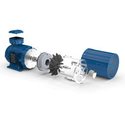
Detailed Photos
Precision planetary gear reducer is another name for planetary gear reducer in the industry. Its main transmission structure is planetary gear, sun gear and inner gear ring.
Compared with other gear reducers, precision planetary gear reducers have the characteristics of high rigidity, high precision (single stage can achieve less than 1 point), high transmission efficiency (single stage can achieve 97% – 98%), high torque/volume ratio, lifelong maintenance-free, etc. Most of them are installed on stepper motor and servo motor to reduce speed, improve torque and match inertia.
Company Profile
Certifications
Packaging & Shipping
| Application: | Motor, Electric Cars, Motorcycle, Machinery |
|---|---|
| Hardness: | Hardened Tooth Surface |
| Installation: | Vertical Type |
| Layout: | Coaxial |
| Gear Shape: | Planetary |
| Step: | Single-Step |
| Samples: |
US$ 100/Piece
1 Piece(Min.Order) | |
|---|

Benefits of a Planetary Motor
A planetary motor has many benefits. Its compact design and low noise makes it a good choice for any application. Among its many uses, planetary gear motors are found in smart cars, consumer electronics, intelligent robots, communication equipment, and medical technology. They can even be found in smart homes! Read on to discover the benefits of a planetary gear motor. You’ll be amazed at how versatile and useful it is!
Self-centering planet gears ensure a symmetrical force distribution
A planetary motor is a machine with multiple, interlocking planetary gears. The output torque is inversely proportional to the diameters of the planets, and the transmission size has no bearing on the output torque. A torsional stress analysis of the retaining structure for this type of motor found a maximum shear stress of 64 MPa, which is equivalent to a safety factor of 3.1 for 6061 aluminum. Self-centering planet gears are designed to ensure a symmetrical force distribution throughout the transmission system, with the weakest component being the pinions.
A planetary gearbox consists of ring and sun gears. The pitch diameters of ring and planet gears are nearly equal. The number of teeth on these gears determines the average gear-ratio per output revolution. This error is related to the manufacturing precision of the gears. The effect of this error is a noise or vibration characteristic of the planetary gearbox.
Another design for a planetary gearbox is a traction-based variant. This design eliminates the need for timing marks and other restrictive assembly conditions. The design of the ring gear is similar to that of a pencil sharpener mechanism. The ring gear is stationary while planet gears extend into cylindrical cutters. When placed on the sun’s axis, the pencil sharpening mechanism revolves around the ring gear to sharpen the pencil.
The JDS eliminates the need for conventional planetary carriers and is mated with the self-centering planet gears by dual-function components. The dual-function components synchronize the rolling motion and traction of the gears. They also eliminate the need for a carrier and reduce the force distribution between the rotor and stator.
Metal gears
A planetary motor is a type of electric drive that uses a series of metal gears. These gears share a load attached to the output shaft to generate torque. The planetary motor is often CNC controlled, with extra-long shafts, which allow it to fit into very compact designs. These gears are available in sizes from seven millimeters to 12 millimeters. They can also be fitted with encoders.
Planetary gearing is widely used in various industrial applications, including automobile transmissions, off-road transmissions, and wheel drive motors. They are also used in bicycles to power the shift mechanism. Another use for planetary gearing is as a powertrain between an internal combustion engine and an electric motor. They are also used in forestry applications, such as debarking equipment and sawing. They can be used in other industries as well, such as pulp washers and asphalt mixers.
Planetary gear sets are composed of three types of gears: a sun gear, planet gears, and an outer ring. The sun gear transfers torque to the planet gears, and the planet gears mesh with the outer ring gear. Planet carriers are designed to deliver high-torque output at low speeds. These gears are mounted on carriers that are moved around the ring gear. The planet gears mesh with the ring gears, and the sun gear is mounted on a moveable carrier.
Plastic planetary gear motors are less expensive to produce than their metal counterparts. However, plastic gears suffer from reduced strength, rigidity, and load capacity. Metal gears are generally easier to manufacture and have less backlash. Plastic planetary gear motor bodies are also lighter and less noisy. Some of the largest plastic planetary gear motors are made in collaboration with leading suppliers. When buying a plastic planetary gear motor, be sure to consider what materials it is made of.
Encoder
The Mega Torque Planetary Encoder DC Geared Motor is designed with a Japanese Mabuchi motor RS-775WC, a 200 RPM base motor. It is capable of achieving stall torque at low speeds, which is impossible to achieve with a simple DC motor. The planetary encoder provides five pulses per revolution, making it perfect for applications requiring precise torque or position. This motor requires an 8mm hex coupling for proper use.
This encoder has a high resolution and is suitable for ZGX38REE, ZGX45RGG and ZGX50RHH. It features a magnetic disc and poles and an optical disc to feed back signals. It can count paulses as the motor passes through a hall on the circuit board. Depending on the gearbox ratio, the encoder can provide up to two million transitions per rotation.
The planetary gear motor uses a planetary gear system to distribute torque in synchrony. This minimizes the risk of gear failure and increases the overall output capacity of the device. On the other hand, a spur gear motor is a simpler design and cheaper to produce. The spur gear motor works better for lower torque applications as each gear bears all the load. As such, the torque capacity of the spur gear motor is lower than that of a planetary gear motor.
The REV UltraPlanetary gearbox is designed for FTC and has three different output shaft options. The output shaft is made of 3/8-inch hex, allowing for flexible shaft replacement. These motors are a great value as they can be used to meet a wide range of power requirements. The REV UltraPlanetary gearbox and motor are available for very reasonable prices and a female 5mm hex output shaft can be used.
Durability
One of the most common questions when selecting a planetary motor is “How durable is it?” This is a question that’s often asked by people. The good news is that planetary motors are extremely durable and can last for a long time if properly maintained. For more information, read on! This article will cover the durability and efficiency of planetary gearmotors and how you can choose the best one for your needs.
First and foremost, planetary gear sets are made from metal materials. This increases their lifespan. The planetary gear set is typically made of metals such as nickel-steel and steel. Some planetary gear motors use plastic. Steel-cut gears are the most durable and suitable for applications that require more torque. Nickel-steel gears are less durable, but are better able to hold lubricant.
Durability of planetary motor gearbox is important for applications requiring high torque versus speed. VEX VersaPlanetary gearboxes are designed for FRC(r) use and are incredibly durable. They are expensive, but they are highly customizable. The planetary gearbox can be removed for maintenance and replacement if necessary. Parts for the gearbox can be purchased separately. VEX VersaPlanetary gearboxes also feature a pinion clamped onto the motor shaft.
Dynamic modeling of the planetary gear transmission system is important for understanding its durability. In previous studies, uncoupled and coupled meshing models were used to investigate the effect of various design parameters on the vibration characteristics of the planetary gear system. This analysis requires considering the role of the mesh stiffness, structure stiffness, and moment of inertia. Moreover, dynamic models for planetary gear transmission require modeling the influence of multiple parameters, such as mesh stiffness and shaft location.
Cost
The planetary gear motor has multiple contact points that help the rotor rotate at different speeds and torques. This design is often used in stirrers and large vats of liquid. This type of motor has a low initial cost and is more commonly found in low-torque applications. A planetary gear motor has multiple contact points and is more effective for applications requiring high torque. Gear motors are often found in stirring mechanisms and conveyor belts.
A planetary gearmotor is typically made from four mechanically linked rotors. They can be used for various applications, including automotive and laboratory automation. The plastic input stage gears reduce noise at higher speeds. Steel gears can be used for high torques and a modified lubricant is often added to reduce weight and mass moment of inertia. Its low-cost design makes it an excellent choice for robots and other applications.
There are many different types of planetary gear motors available. A planetary gear motor has three gears, the sun gear and planet gears, with each sharing equal amounts of work. They are ideal for applications requiring high torque and low-resistance operation, but they require more parts than their single-stage counterparts. The steel cut gears are the most durable, and are often used in applications that require high speeds. The nickel-steel gears are more absorptive, which makes them better for holding lubricant.
A planetary gear motor is a high-performance electrical vehicle motor. A typical planetary gear motor has a 3000 rpm speed, a peak torque of 0.32 Nm, and is available in 24V, 36V, and 48V power supply. It is also quiet and efficient, requiring little maintenance and offering greater torque to a modern electric car. If you are thinking of buying a planetary gear motor, be sure to do a bit of research before purchasing one.
editor by CX 2023-06-12